152/267
Building Technologies Basic documentation LMV37.4... CC1P7546en
15 Connection and internal diagram 17.12.2018
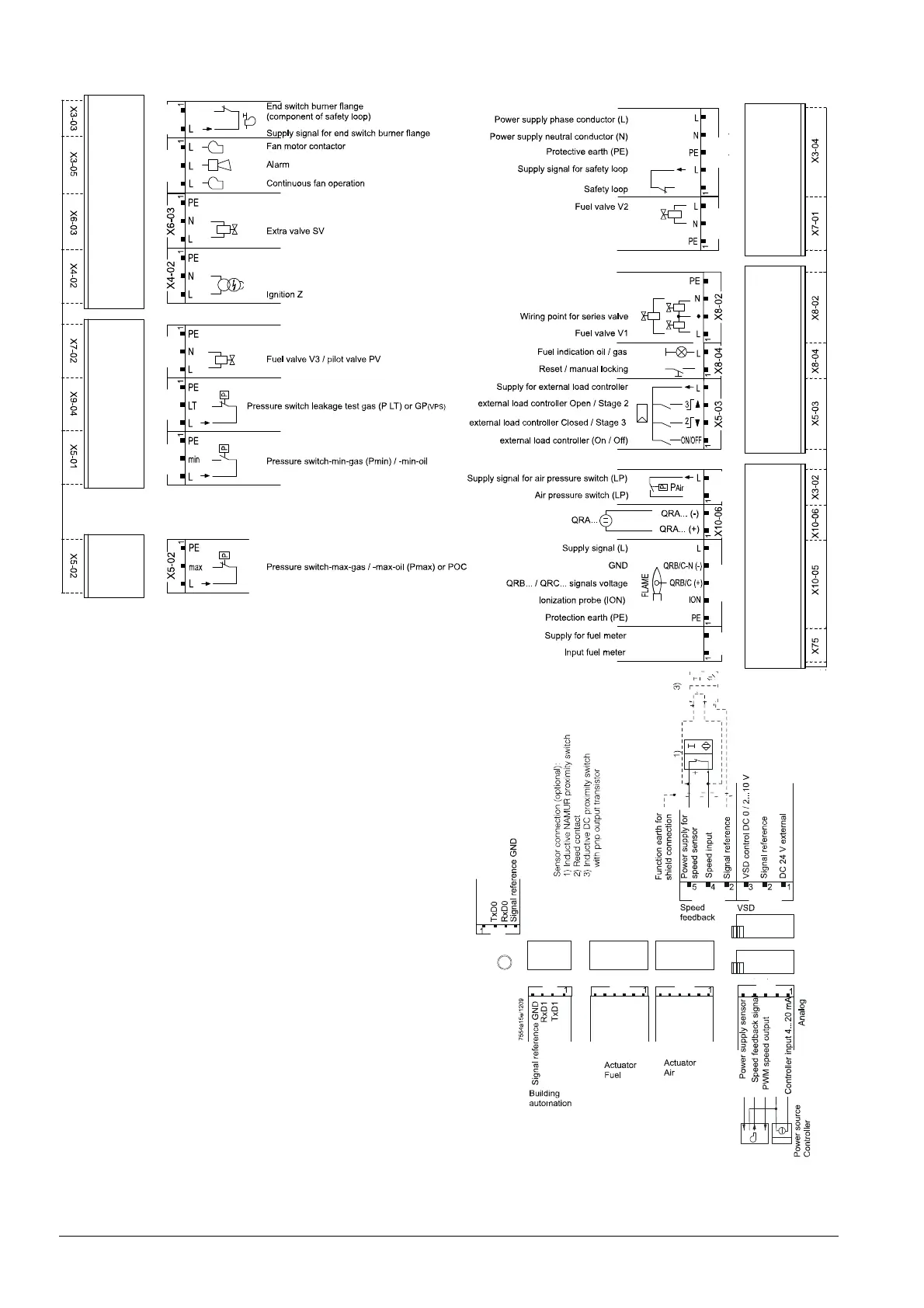
15 Connection and internal diagram
X3-03X3-05
X3-04
X7-01
X75 X10-05 X3-02
X5-01
X9-04 X7-02
11111 11 1 1
111111
1
1
7546a14e/0718
+
Shielding:
For shielding the cables on the VSD, refer to:
Siemens SED2 VSD Commissioning Manual (G5192),
chapters 4 and 7, or
Danfoss Operation Manual VLT 6000 (MG60A703),
chapter Installation
VSD X74
X64
1
1
COM X92 FUEL X54 AIR X53
BCI
X56
11
1
GND
PWM fan
ACT1_IN_B
ACT1_IN_A
ACT1_OUT_B
ACT1_OUT_A
GND
UAC_SA
ACT0_IN_B
ACT0_IN_A
ACT0_OUT_B
ACT0_OUT_A
GND
UAC_SA
DC 5 V
DC 5 V
Display / BCI
Figure 94: Inputs and outputs
 Loading...


