186/267
Building Technologies Basic documentation LMV37.4... CC1P7546en
27 Parameter level 17.12.2018
P
Vh
min s %
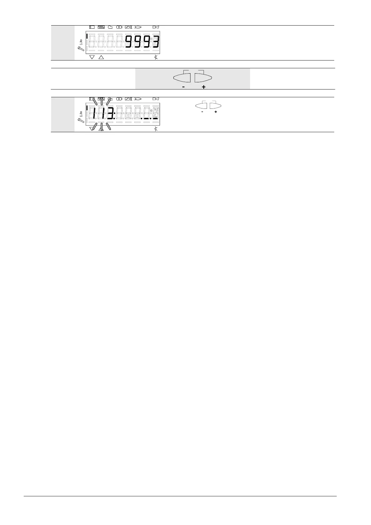
Bild 55/0707
The display no longer flashes.
Example: Burner identification 9993
ES
P
V
hmin
s%
Bild 49/0707
Press
ESC
to return to the parameter level.
PArAmeter 113: for burner identification.

 Loading...

