70/267
Building Technologies Basic documentation LMV37.4... CC1P7546en
7 Basic unit LMV37.4 17.12.2018
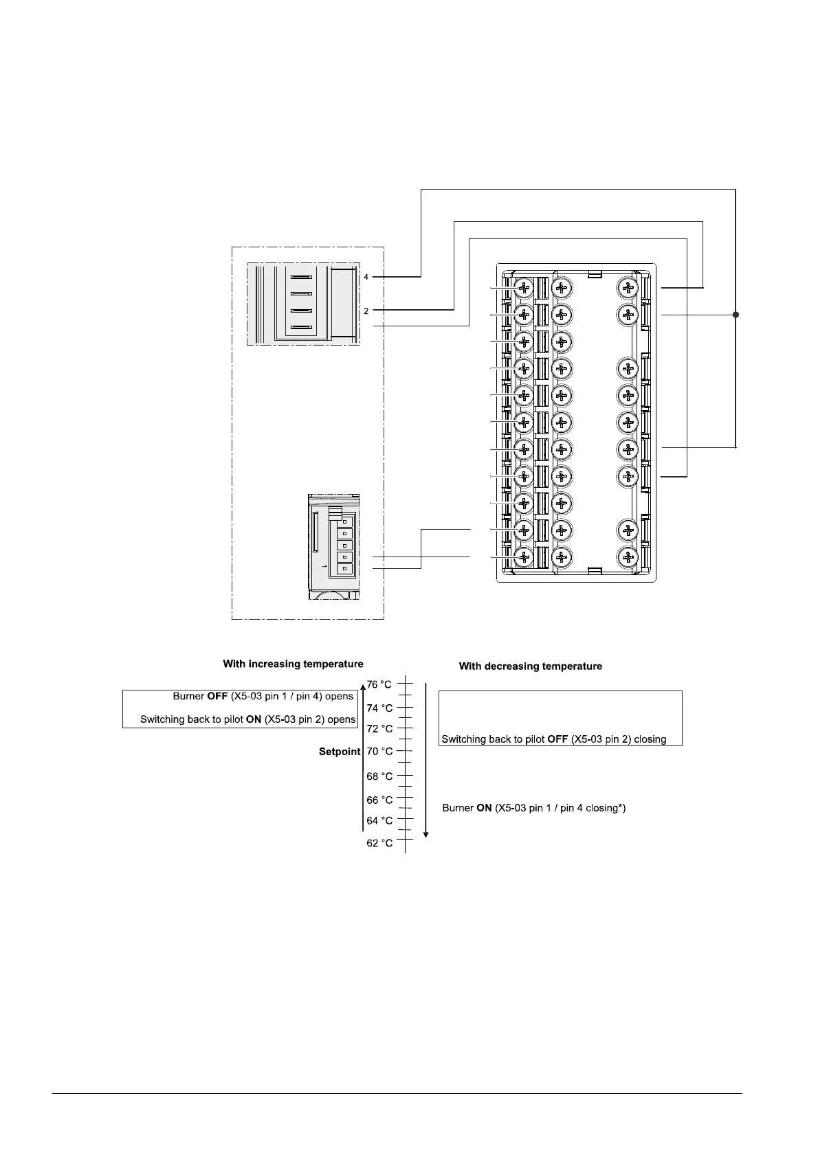
RWF55 application examples:
The setting must be set to low active to use the RWF55. The load controller ON signal
(X5-03 pin 1 / pin 4) is applied at RWF55 (contacts 1P and 1N). The signal for switching
back to pilot (X5-03 pin 2) is connected to RWF55 (contacts 6N and 6P). Function Ik5
must be selected at RWF55.
The output is preselected via a 4…20 mA analog signal.
11
12
13
14
21
22
23
31
32
A+
A-
C1
C2
C3
C4
R+
R-
G+
G-
D1
D2
DG
6N
6P
K3
KQ
K2
1P
1N
N
L1
LMV...
X5-03
1
X64
Bild 431e/0913
5
4
3
2
1
3
(4...20 mA)
(L)
(ON/OFF)
RWF55...
Figure 40: Wiring LMV37.4 with universal controller RWF55
Main flame Main flame
OFF
ON
Bild 428e/0913
Figure 41: Switching back to pilot sequence in connection with an RWF55 universal controller
*) The burner ON threshold is only active when switching on (cold start)
The Switching back to pilot function is active in the marked temperature zone. If the
temperature increases above the ON threshold, the Switching back to pilot function is
activated. The main flame is shut down at the same time. If the temperature decreases
in the direction of the setpoint, the Switching back to pilot function remains active until
the temperature falls below the OFF threshold.
The main flame is switched back on.

 Loading...

