EasyManua.ls Logo

Siemens MICROMASTER 440 - User Manual

Siemens MICROMASTER 440
312 pages
Print Icon
To Next Page IconTo Next Page
Loading...
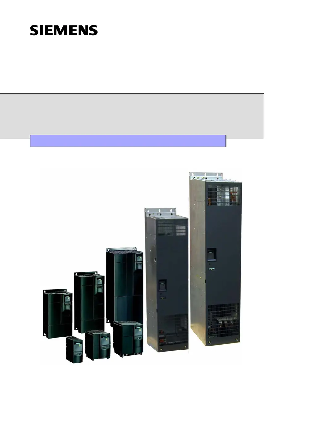
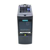
MICROMASTER 440
0.12 kW - 250 kW
Operating Instructions Issue 10/06
User Documentation
6SE6400-5AW00-0BP0

Table of Contents

Other manuals for Siemens MICROMASTER 440

Questions and Answers

  • P
    petersonjoySep 6, 2025
    Why does my Siemens MICROMASTER 440 motor fail to run after changing the parameters?
    • M
      Michael LynchSep 6, 2025
      If your Siemens Inverter Drive motor fails to run after changing the parameters, try resetting the inverter to the factory default parameter values by setting P0010 = 30, then P0970 = 1, and pressing P. Another approach is to use a switch between terminals 5 and 9; the drive should then run to the defined setpoint by analogue input.
  • R
    Raymond MoralesAug 22, 2025
    What to do if my Siemens Power Supply shows F0001 Overcurrent?
    • N
      Nicole ColeAug 22, 2025
      If your Siemens Power Supply is showing an F0001 Overcurrent error, it could be due to several reasons. First, ensure that the motor power (P0307) corresponds to the inverter power (P0206). Also, check that you haven't exceeded cable length limits, and inspect the motor cable and motor for short-circuits or earth faults. Verify that the motor parameters match the motor in use and that the value of stator resistance (P0350) is correct. Finally, make sure the motor isn't obstructed or overloaded. You might also try increasing the ramp time or reducing the boost level.
  • C
    conniecollinsSep 3, 2025
    What to do if the Siemens Power Supply motor won't run after changing parameters?
    • C
      Cheyenne OrtizSep 3, 2025
      If the motor fails to run after you've changed the parameters on your Siemens Power Supply, try setting P0010 = 30, then P0970 = 1, and press P to reset the inverter to the factory default parameter values. Alternatively, use a switch between terminals 5 and 8 on the control board; the drive should then run to the defined setpoint by analogue input.
  • R
    racheljamesSep 2, 2025
    What causes F0011 Motor Over-temperature on my Siemens Power Supply?
    • D
      dsalinasSep 2, 2025
      If your Siemens Power Supply shows a F0011 Motor Over-temperature error, the motor may be overloaded. First, check the motor data and loading. Then, examine if the boost settings are too high (P1310, P1311, P1312). Also, check the parameter for the motor thermal time constant and the parameter for the motor I2t warning level.
  • M
    Mr. Richard Morales IIISep 1, 2025
    What does F0005 Inverter I t mean on my Siemens Power Supply and how can I resolve it?
    • J
      johnsonlaurenSep 1, 2025
      If your Siemens Power Supply shows the F0005 Inverter I t error, the inverter might be overloaded. Verify that the load duty cycle is within specified limits and that the motor power (P0307) matches the inverter power (P0206).
  • T
    Travis TaylorAug 30, 2025
    How to fix F0004 Inverter Over-temperature on a Siemens Power Supply?
    • J
      Jessica MillerAug 30, 2025
      If your Siemens Power Supply displays the F0004 Inverter Over-temperature error, the ventilation may be inadequate. Here's what to check: * Ensure the fan is turning when the inverter is running. * Verify the pulse frequency is set to the default value. * Check for any obstructions of the air inlet and outlet points. Also, the ambient temperature could be higher than specified for the inverter.
  • L
    laura92Aug 29, 2025
    What causes F0003 Undervoltage on my Siemens Power Supply?
    • A
      Amanda GonzalesAug 29, 2025
      If your Siemens Power Supply is showing an F0003 Undervoltage error, it could be due to a main supply failure. Ensure that the supply voltage (P0210) is within the limits indicated on the rating plate and that the supply isn't susceptible to temporary failures or voltage reductions.
  • C
    Charles LarsonAug 27, 2025
    How to troubleshoot a Siemens Power Supply motor that won't start after giving the ON command?
    • R
      rhuffAug 27, 2025
      If the motor fails to start on your Siemens Power Supply when the ON command is given, verify the following: Check that P0010 = 0. Ensure a valid ON signal is present. Confirm that P0700 = 2 (for digital input control) or P0700 = 1 (for BOP control). Also, check that the setpoint is present (0 to 10V on Terminal 3) or the setpoint has been entered into the correct parameter, depending upon the setpoint source (P1000).
  • K
    katherine02Aug 26, 2025
    What to do if my Siemens Power Supply shows F0002 Overvoltage?
    • P
      Patricia GonzalesAug 27, 2025
      If your Siemens Power Supply displays an F0002 Overvoltage error, it means the DC-link voltage (r0026) exceeds the trip level (P2172). Here’s what you should check: Ensure the supply voltage (P0210) is within the limits indicated on the rating plate. Verify that the DC-link voltage controller is enabled (P1240) and properly parameterized. The ramp-down time (P1121) should match the inertia of the load. Also, confirm that the required braking power is within specified limits. Remember, higher inertia requires longer ramp times; otherwise, consider using a braking resistor.
  • C
    Christopher StevensAug 25, 2025
    What to do if Siemens DC Drives motor fails to run after changing the parameters?
    • P
      Patricia SimonAug 25, 2025
      If a Siemens DC drive motor fails to run after you've changed the parameters, try resetting the inverter to its factory default parameter values. To do this, set P0010 = 30, then set P0970 = 1, and press P. You can also use a switch between terminals 5 and 9 (Figure 3-14). The drive should then run to the defined setpoint by analogue input.

Summary

Overview

The MICROMASTER 440

General introduction to the MICROMASTER 440 frequency inverter series.

Features

Lists the main characteristics and performance features of the MICROMASTER 440.

Installation

Installation after a Period of Storage

Procedure for reforming capacitors after prolonged storage.

Ambient operating conditions

Details temperature, humidity, altitude, shock, vibration, and radiation requirements.

Mechanical installation

Guidelines for mounting, including clearances and handling.

Electrical installation

Instructions for grounding, wiring, and connections, including EMI avoidance.

Functions

Parameters

Explains parameter types, attributes, and how to set/monitor them.

Operator panels for MICROMASTER

Describes the BOP and AOP, their displays, keys, and functions.

Block diagram

Provides a system overview of the MICROMASTER 440's functional blocks and connections.

Factory setting

Details the default parameters and conditions for out-of-the-box operation.

Commissioning

Outlines the procedures for commissioning the drive, including quick and series methods.

Troubleshooting

Troubleshooting with the SDP

Explains how to interpret LED states on the Status Display Panel (SDP) for diagnosis.

Troubleshooting with the BOP

Provides guidance for diagnosing issues using the Basic Operator Panel (BOP).

Fault messages

Lists methods for resetting fault codes and where to find detailed descriptions.

Alarm Messages

Explains where alarm messages are stored and how to access their detailed descriptions.

MICROMASTER 440 specifications

Table 5-1 MICROMASTER 440 Performance Ratings

Lists performance specifications like voltage, frequency, overload capability, and inputs/outputs.

Table 5-2 Dimensions, required cooling air flow and tightening torques for power terminals

Provides physical dimensions, cooling requirements, and torque specifications.

Table 5-3 Current reduction depending on pulse frequency

Details current derating values based on pulse frequency and mains voltage.

Table 5-4 Data for braking resistors

Lists data for braking resistors, including IDC_max and resistance values.

Table 5-5 MICROMASTER 440 Specifications

Contains technical specifications for individual MICROMASTER 440 inverters, including order numbers and cable sizes.

Options

Inverter-independent options

Lists optional components like operator panels, communication modules, and commissioning tools.

Inverter-dependent options

Details options that depend on the inverter frame size, like filters and chokes.

Electro-magnetic compatibility (EMC)

Electro-magnetic compatibility

Explains EMC requirements and routes for demonstrating compliance (self-certification, technical file, EC certificate).

Short circuit current rating (SCCR)

Frame Sizes A to C

Specifies standard and high SCCR values for frame sizes A to C, including UL compliance.

Frame Sizes D to GX

Details standard and high SCCR values for frame sizes D to GX, including NEC and UL requirements.

Standards

European Low Voltage Directive

Lists compliance with Low Voltage Directive and relevant standards like EN 61800-5-1.

European EMC Directive

States compliance with EMC Directive when installed per manual recommendations.

Underwriters Laboratories

Notes UL and CUL LISTED POWER CONVERSION EQUIPMENT certification.

ISO 9001

Mentions Siemens' ISO 9001 quality management system compliance.

List of Abbreviations

Siemens MICROMASTER 440 Specifications

General IconGeneral
Power Range0.12 kW to 250 kW
Output Voltage0 V to Input Voltage
Output Frequency0 Hz to 650 Hz
Control ModesVector control
Overload Capability150% for 60 seconds
Protection FeaturesOvervoltage, Undervoltage, Overcurrent, Overtemperature, Short Circuit, Ground Fault
Communication InterfacesPROFIBUS, DeviceNet, CANopen, Modbus RTU
Enclosure RatingIP20
Ambient Temperature-10°C to +50°C
Input Voltage200 V to 240 V (±10%), 380 V to 480 V (±10%)

Related product manuals