Connecting
7.3 Connecting components
SIMATIC MV420 / SIMATIC MV440
124 Operating Instructions, 04/2013, A5E02371045-06
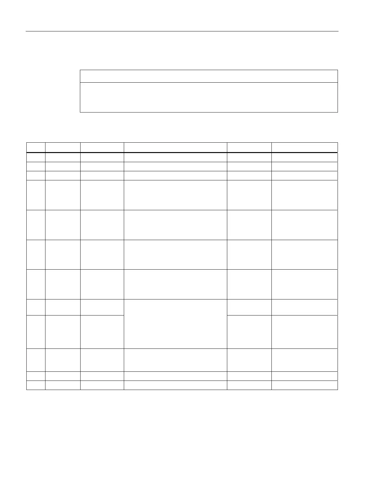
Pin assignment of the Power IO RS232 cable
NOTICE
INPUT - COMMON / OUTPUT - COMMON must be connected
INPUT - COMMON / OUTPUT - COMMON must be connected before you can use the
inputs and outputs detailed below.
Table 7- 1 SIMATIC MV440
Pin Color Signal name Possible values Default Meaning
H Red 24 V DC Power supply
G Blue 0 V Power supply
K Violet INPUT1 TRG TRG Trigger input
D Yellow INPUT /
OUTPUT2
DISA, SEL0, SEL1, SEL2, SEL3, TRN,
RES, IN_OP, TRD, RDY, READ,
MATCH, N_OK, EXT_1, EXT_2,
EXT_3, EXT_4
IN_OP Freely selectable input
or output.
L Gray/
pink
INPUT /
OUTPUT3
DISA, SEL0, SEL1, SEL2, SEL3, TRN,
RES, IN_OP, TRD, RDY, READ,
MATCH, N_OK, EXT_1, EXT_2,
EXT_3, EXT_4
RDY Freely selectable input
or output.
C Green INPUT /
OUTPUT4
DISA, SEL0, SEL1, SEL2, SEL3, TRN,
RES, IN_OP, TRD, RDY, READ,
MATCH, N_OK, EXT_1, EXT_2,
EXT_3, EXT_4
READ Freely selectable input
or output.
B Brown INPUT /
OUTPUT5
DISA, SEL0, SEL1, SEL2, SEL3, TRN,
RES, IN_OP, TRD, RDY, READ,
MATCH, N_OK, EXT_1, EXT_2,
EXT_3, EXT_4
N_OK Freely selectable input
or output.
A White INPUT -
COMMON
Reference point 0 V or
24 V for inputs.
E Gray OUTPUT -
COMMON
P type inputs/outputs:
INPUT - COMMON = 0 V and
OUTPUT - COMMON = + 24 V DC
N type inputs/outputs:
INPUT - COMMON = + 24 V DC and
OUTPUT - COMMON = 0 V
Reference point 0 V or
24 V for outputs.
J Black STROBE
(OUTPUT)
Signal output for
connecting external
flashes
F Pink RS232 TXD RS232 send line
M Red/blue RS232 RXD RS232 receive line