Connecting
7.3 Connecting components
SIMATIC MV420 / SIMATIC MV440
Operating Instructions, 04/2013, A5E02371045-06
125
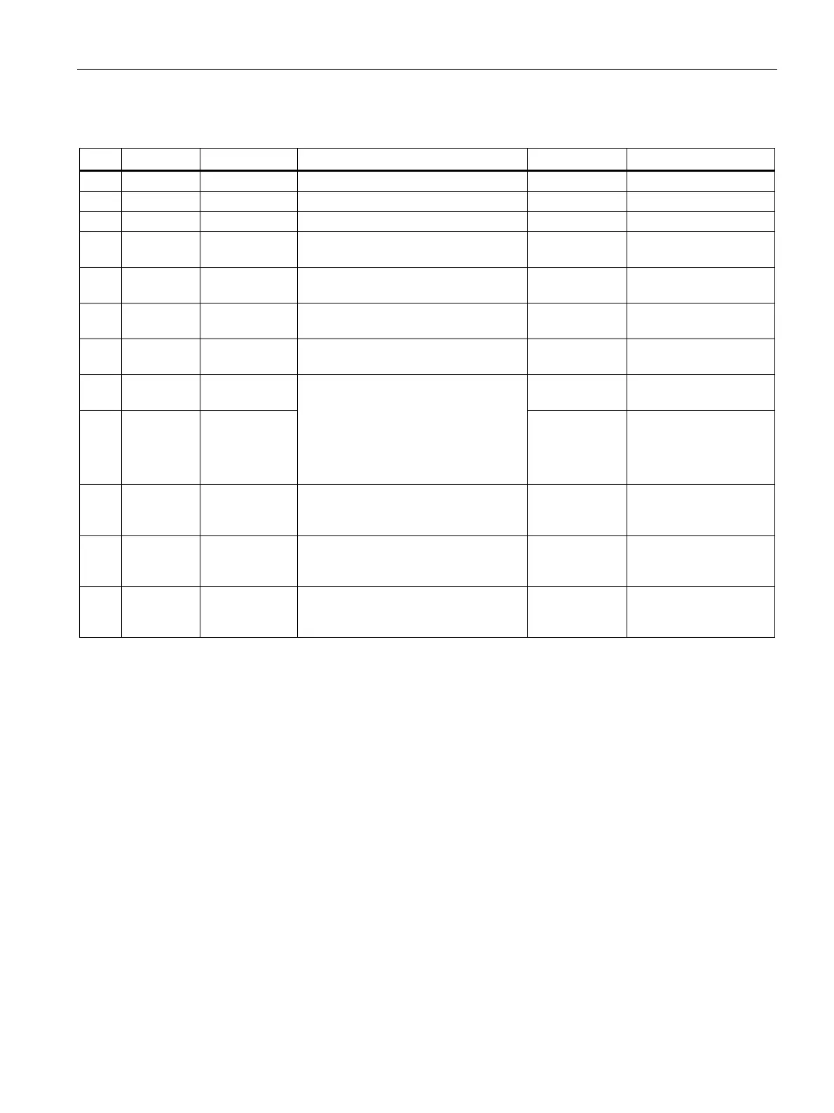
Table 7- 2 SIMATIC MV420
Pin Color Signal name Possible values Default Meaning
H Red 24 V DC Power supply
G Blue 0 V Power supply
K Violet INPUT1 TRG TRG Trigger input
D Yellow OUTPUT2 IN_OP, TRD, RDY, READ, MATCH,
N_OK, EXT_1, EXT_2, EXT_3, EXT_4
RDY Freely selectable output
L Gray/
pink
OUTPUT3 IN_OP, TRD, RDY, READ, MATCH,
N_OK, EXT_1, EXT_2, EXT_3, EXT_4
READ Freely selectable output
C Green ASM TxD_N TxD_N signal of the
ASM interface
B Brown ASM TxD_P TxD_P signal of the
ASM interface
A White INPUT -
COMMON
Reference point 0 V or
24 V for inputs.
E Gray OUTPUT -
COMMON
P type inputs/outputs:
INPUT - COMMON = 0 V and
OUTPUT - COMMON = + 24 V DC
N type inputs/outputs:
INPUT - COMMON = + 24 V DC and
OUTPUT - COMMON = 0 V
Reference point 0 V or
24 V for outputs.
J Black STROBE
(OUTPUT)
Signal output for
connecting external
flashes
F Pink RS 232 TxD or
ASM RxD_P
RS232 TxD, ASM RxD_P RS232 TXD RS232 send line or
ASM RxD_P of the ASM
interface
M Red/blue RS232 RxD or
ASM RxD_N
RS232 RxD,ASM RxD_N RS232 RXD RS232 receive line or
ASM RxD_N of the ASM
interface
MV400 push-pull power cable cable pin assignment
See Technical specifications of the interfaces (Page 359).
ASM cable
The co
nnectors are already fitted to the ASM cable.
● Using the ASM cable, you connect the communication modules, for example RF180C
and ASM456.
For SIMATIC MV420, a special ASM cable with M16 socket is available. Refer to the
chapter "Cables" (Page 370).