Connecting
7.3 Connecting components
SIMATIC MV420 / SIMATIC MV440
126 Operating Instructions, 04/2013, A5E02371045-06
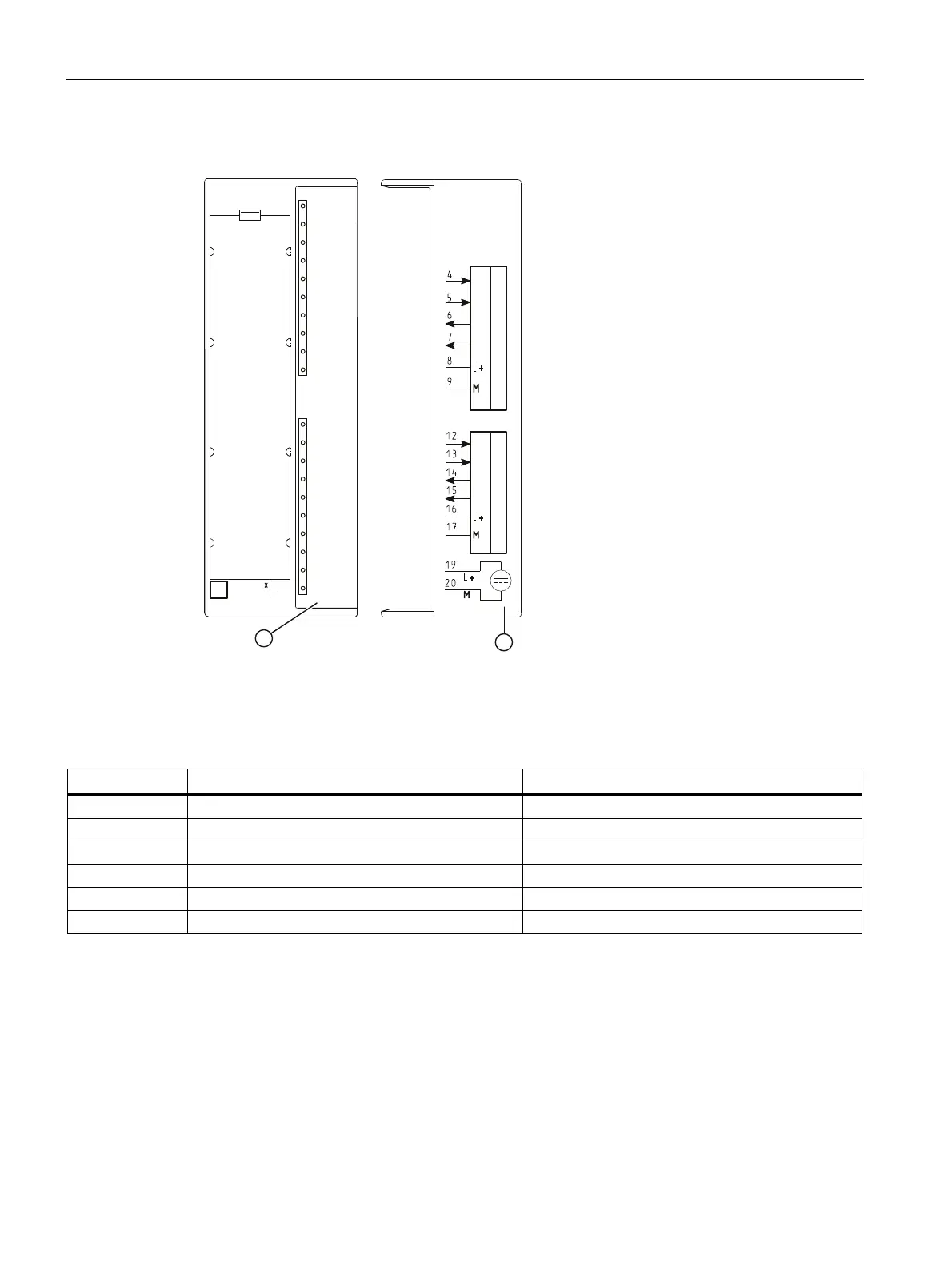
The following cable assignment is defined for the connection to the ASM 475:
6
6
(
(
6
6
(
(
$60
6)
'&9
$&7B
(55B
35(B
5['B
$&7B
(55B
35(B
5['B
02%<
*7*$
6/*6/*
① Status and error displays
② Wiring diagram; the numbers of the connection refer to the X1 connector of the upper housing
Figure 7-2 Front panel and inside of the front door of the ASM475 module
Pin M16 socket Wire color of the connecting cable Terminal ASM475 (Channel 1/Channel 2)
H Red 8 / 16
G Blue 9 / 17
F Pink 4 / 12
M Red/blue 5 / 13
B Brown 6 / 14
C Green 7 / 15
Ethernet cable M12/RJ-45
● With a preassembled Ethernet cable, you connect a PC / PG to control and operate the
reader.
● Attach the Ethernet cable to a switch to connect the reader to an automation system via
onboard PROFINET IO.