Configuration
5.3 Examples
1FN3 linear motors
134 Configuration Manual, 10/2018, 6SN1197-0AB86-0BP2
Calculating the pressure drop
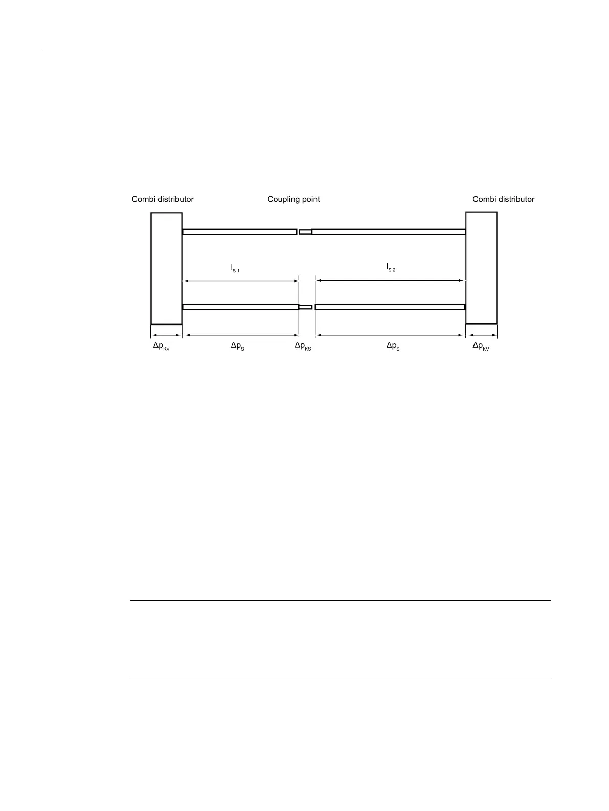
Pressure drop in the secondary section cooling system
The secondary section cooling comprises a coupling point and two combi distributors.
The parallel heatsink profiles for the 1FN3300 have a length of l
s 1
= 0.716 m (4 secondary
sections) and l
s 2
= 0.900 m (5 secondary sections).
Figure 5-17 Example of a secondary section cooling system
In total, the pressure drop of the secondary section cooling system is:
Δp
S,ges
= Δp
S
‧ l
S 1
+ Δp
S
‧ l
S 2
+ 2 ‧ Δp
KV
+ Δp
KS
The result is:
Δp
S,ges
= 0.09 bar/m ‧ 0.176 m +0.09 bar/m ‧ 0.900 m + 2 ‧ 0.42 bar + 0.31 bar
Δp
S,ges
= 1.25 bar
Total cooling
For the total cooling, the following results:
Δp
gesamt
= Δp
P,H
+ Δp
P,P
+ Δp
S,ges
= 0.32 bar + 0.33 bar + 1.25 bar
gesamt
=
Note
Pressure drop across the water lines on the customer side
For the total pressure drop, the pressure drop across wat
er connections on the customer
side caused by the cooling medium pump
- combi distributor hoses or valves must also be

 Loading...


