Configuration
5.3 Examples
1FN3 linear motors
Configuration Manual, 10/2018, 6SN1197-0AB86-0BP2
135
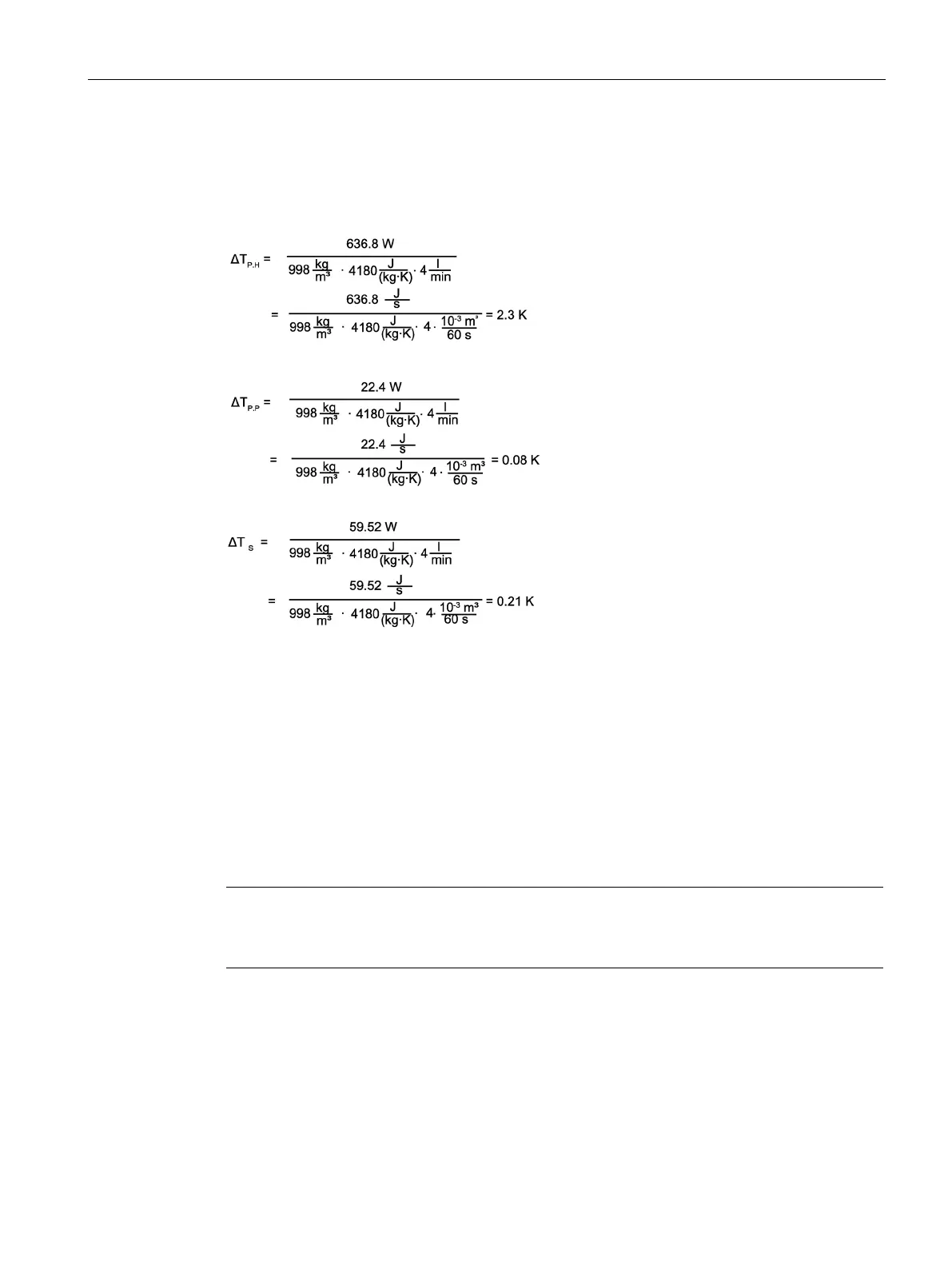
Calculating the temperature rise
Individual cooling circuits
The values for the individual cooling circuits are calculated as follows:
Total cooling
For the total cooling, the following results:
ΔT
gesamt
= ΔT
P,H
+ ΔT
P,P
+ ΔT
S,ges
= 2.3 K + 0.08 K + 0.21 K
gesamt
=
For a heat-exchanger unit to be able to cool the motor under the conditions described in this
section, it must be dimensioned for about 720 W. The pressure drop is around 3 bar and the
temperature difference between the flow and return lines of the cooling system is around
3 K.
Note
Recommended manufacturers
You will find the recommended manufacturers for the heat
-exchanger units in the appendix.

 Loading...


