EasyManuals Logo

Siemens SIMOTICS L-1FN3 Configuration Manual

Siemens SIMOTICS L-1FN3
600 pages
To Next Page IconTo Next Page
To Previous Page IconTo Previous Page
Page #504 background imageLoading...
Page #504 background image
Electrical connection
8.3 System integration
1FN3 linear motors
502 Configuration Manual, 10/2018, 6SN1197-0AB86-0BP2
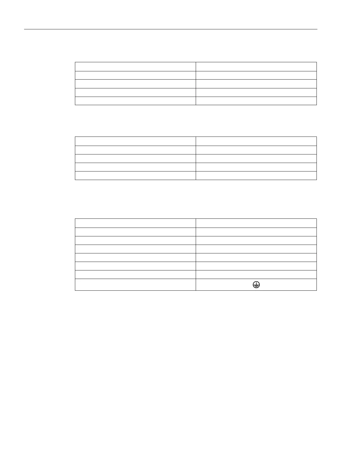
Table 8- 5 Conductor assignments of the temperature sensor cables – Table A
Conductor color
Interface
White
-1R2: -KTY or Pt1000
black +1R1: +KTY or Pt1000
red
1TP1: PTC
Yellow 1TP2: PTC
Applies to permanently connected combination cable with open conductor ends for 1FN3050
Table 8- 6 Conductor assignments of the temperature sensor cables – Table B
Conductor color
Interface
White
-1R2: -KTY or Pt1000
Brown
+1R1: +KTY or Pt1000
Green
1TP1: PTC
Yellow
1TP2: PTC
Applies to cable 6FX8002
-2SL01-..., 6FX8002-2SL02-..., 6FX8002-2SL20-... and permanently
connected sensor cable with open conductor ends for 1FN3050
Table 8- 7 Conductor assignments of the temperature sensor cables – Table C
Conductor color
Pin
White
1
Brown
2
Green
3
Yellow
4
Gray
5
Pink
6
Green/yellow
Applies to cable 6FX8002
-2SL00-...; the conductor colors also apply for cable 6FX8002-1BD00-...
(sold by the meter)

Table of Contents

Other manuals for Siemens SIMOTICS L-1FN3

Questions and Answers:

Question and Answer IconNeed help?

Do you have a question about the Siemens SIMOTICS L-1FN3 and is the answer not in the manual?

Siemens SIMOTICS L-1FN3 Specifications

General IconGeneral
BrandSiemens
ModelSIMOTICS L-1FN3
CategoryEngine
LanguageEnglish

Related product manuals