EasyManuals Logo

Siemens SIMOTICS L-1FN3 Configuration Manual

Siemens SIMOTICS L-1FN3
600 pages
To Next Page IconTo Next Page
To Previous Page IconTo Previous Page
Page #507 background imageLoading...
Page #507 background image
Electrical connection
8.3 System integration
1FN3 linear motors
Configuration Manual, 10/2018, 6SN1197-0AB86-0BP2
505
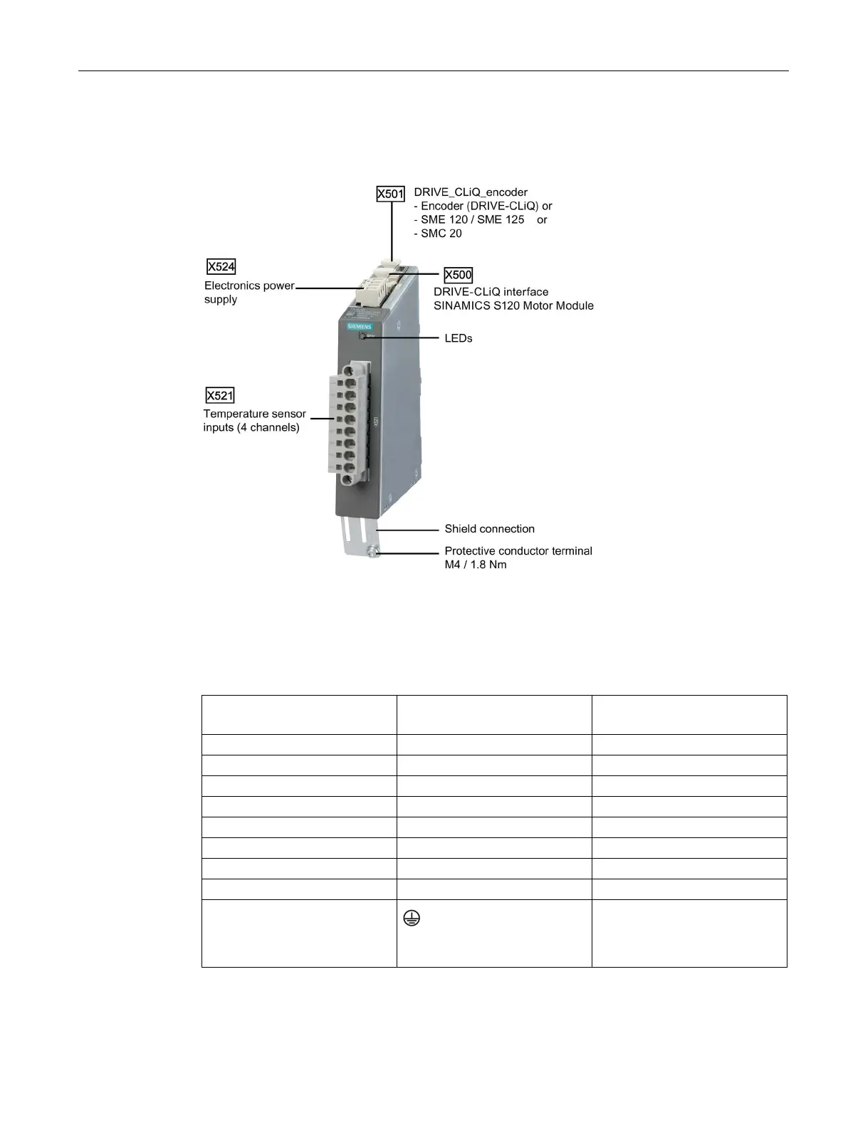
Connection of the temperature sensors via TM120
The terminal assignment for the channels of the temperature sensor inputs can be freely
selected on the TM120.
Table 8- 9 Terminal assignment for the temperature sensor inputs on the TM120 (example)
Conductor assignment for cable
6FX8002-2SL00- ....
Duct / clamp
Sensor contact
white
1
-1R2: -KTY or Pt1000
brown
2
+1R1: +KTY or Pt1000
green
3
1TP1: PTC
yellow
4
1TP2: PTC
gray
5
-
pink
6
-
-
7
-
-
8
-
green/yellow
Protective conductor connection
on the shield connection plate
PE

Table of Contents

Other manuals for Siemens SIMOTICS L-1FN3

Questions and Answers:

Question and Answer IconNeed help?

Do you have a question about the Siemens SIMOTICS L-1FN3 and is the answer not in the manual?

Siemens SIMOTICS L-1FN3 Specifications

General IconGeneral
BrandSiemens
ModelSIMOTICS L-1FN3
CategoryEngine
LanguageEnglish

Related product manuals