Electrical installation
4.5 Connections
Cabinet Modules NEMA
102 Manual, 04/2014, A5E03586450A
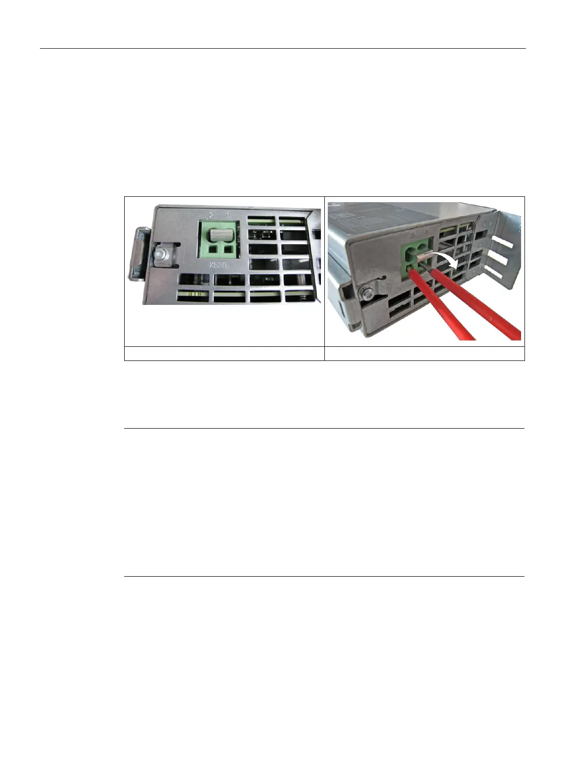
Removing the connector jumper in the VSM10 Voltage Sensing Module
If a Smart Line Module or Active Line Module is operated on an ungrounded system (IT
system), the connector jumper in terminal X530 on the button of the component must be
removed from the Voltage Sensing Module (VSM10).
The position of the Voltage Sensing Module must be obtained from the previous drawings.
Use two screwdrivers or a suitable tool in order to relieve the holding springs in the terminal
and then pull the connector jumper.
Terminal X530 with connector jumper
Relieve the springs and pull the connector jumper
Note
Preassignment and position of the customer terminal block
The factory setting and description of the customer terminal blocks can be found in the circuit
diagrams.
f the customer terminal blocks of the individual Cabinet Modules is indicated in
The interfaces or customer terminal blocks are documented for the respective Cabinet
Modules.
-CLiQ cables must be locally routed according to the customer-specific engineering
specifications for the entire system.

 Loading...


