Options
8.34 L61/L62, L64/L65, braking units
Cabinet Modules NEMA
Manual, 04/2014, A5E03586450A
469
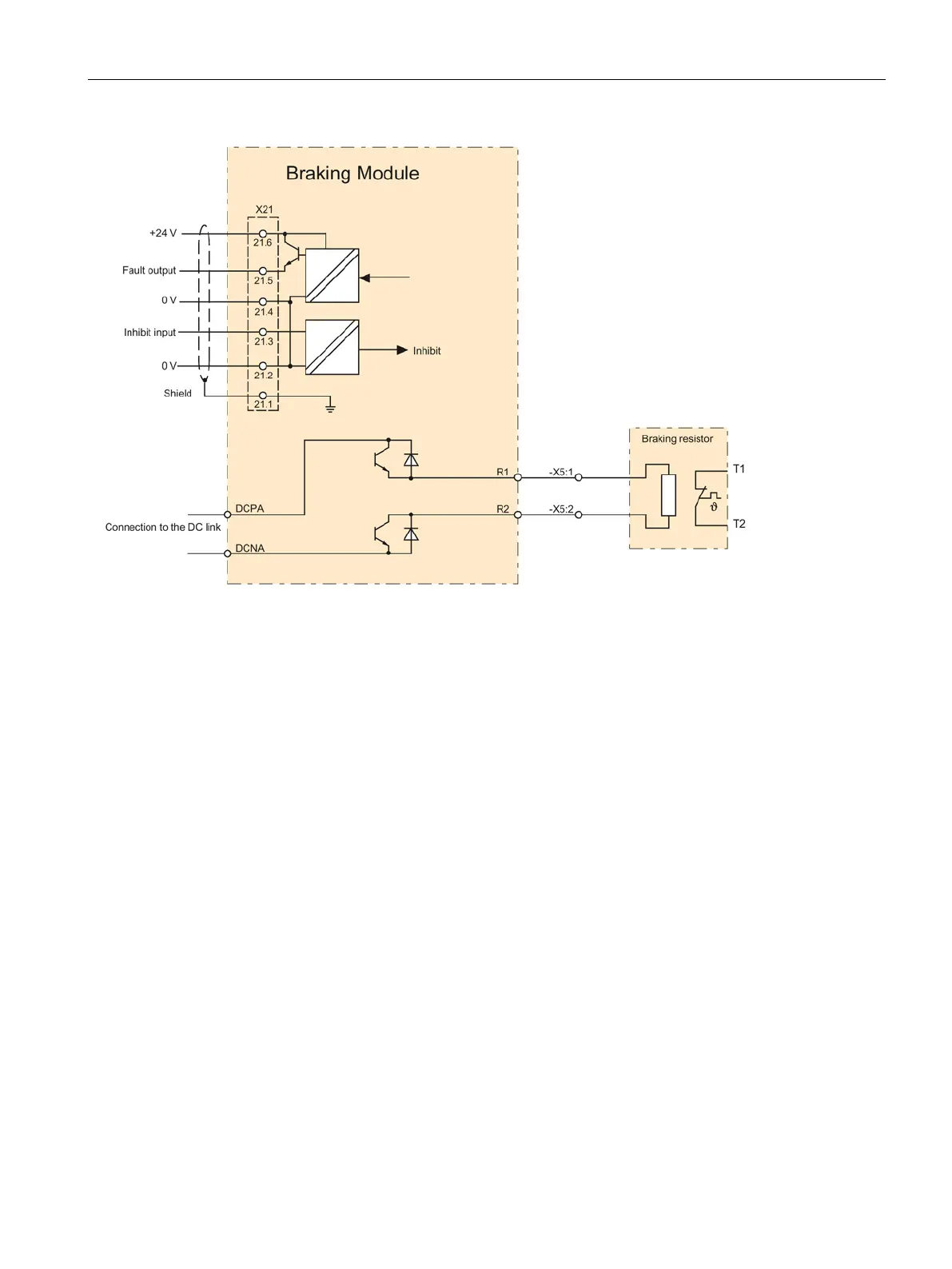
Figure 8-44 Example connection of Braking Module
Braking resistors
Description
The excess energy of the DC link is dissipated via the braking resistor.
The braking resistor is connected to a braking module. The braking resistor is positioned
outside the cabinet or switchgear room. This enables the resulting heat loss around the
Basic Line Module, Smart Line Module, Active Line Module, or Motor Module to be
dissipated, thereby reducing the amount of air conditioning required.
Resistors with a rated power (continuous power) of 25 kW and 50 kW are available.
A thermostatic switch monitors the braking resistor for overtemperature and issues a signal
on a floating contact if the limit value is exceeded.

 Loading...


