Options
8.34 L61/L62, L64/L65, braking units
Cabinet Modules NEMA
472 Manual, 04/2014, A5E03586450A
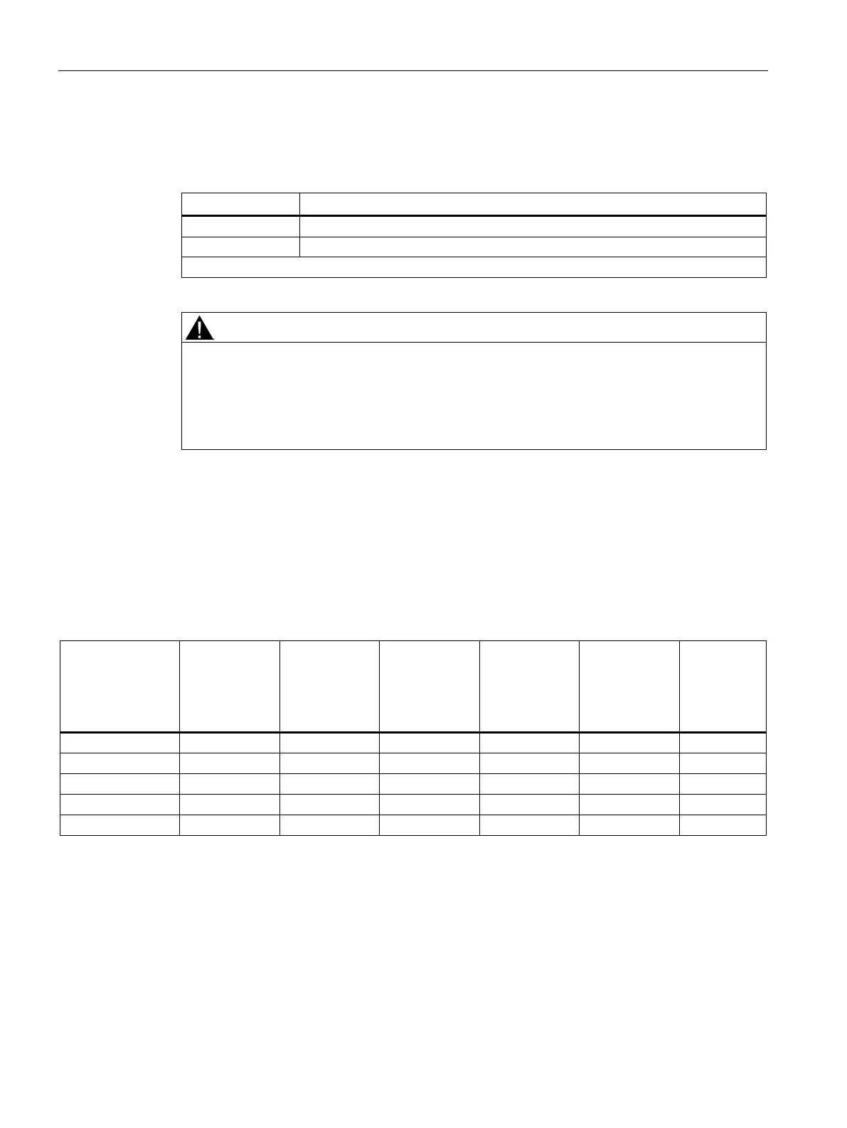
Table 8- 55 Thermostatic switch connection
Thermostatic switch connection
Thermostatic switch connection
Max. connectable cross-section #16 AWG (1.5 mm²)
Risk of death from fire when thermostatic switch evaluation is not available
When evaluation of the thermostatic switch is not available, there is a risk of fire leading to
death or serious injury.
• If you evaluate the thermostatic switch by the Control Unit or a higher-level controller, a
shutdown must be performed, if necessary.
Technical specifications
Load data for the braking units
Table 8- 56 Load data for the braking units
Braking
Module
continuous
power
P
DB
Braking
Module
peak power
P
15
380 ... 480 V 25 kW 125 kW 100 kW 50 kW 4.4 Ω ± 7.5% 189 A
500 ... 600 V 50 kW 250 kW 200 kW 100 kW 3.4 Ω ± 7.5% 306 A

 Loading...


