Cabinet Modules
5.3 Smart Line Modules
Cabinet Modules NEMA
Manual, 04/2014, A5E03586450A
177
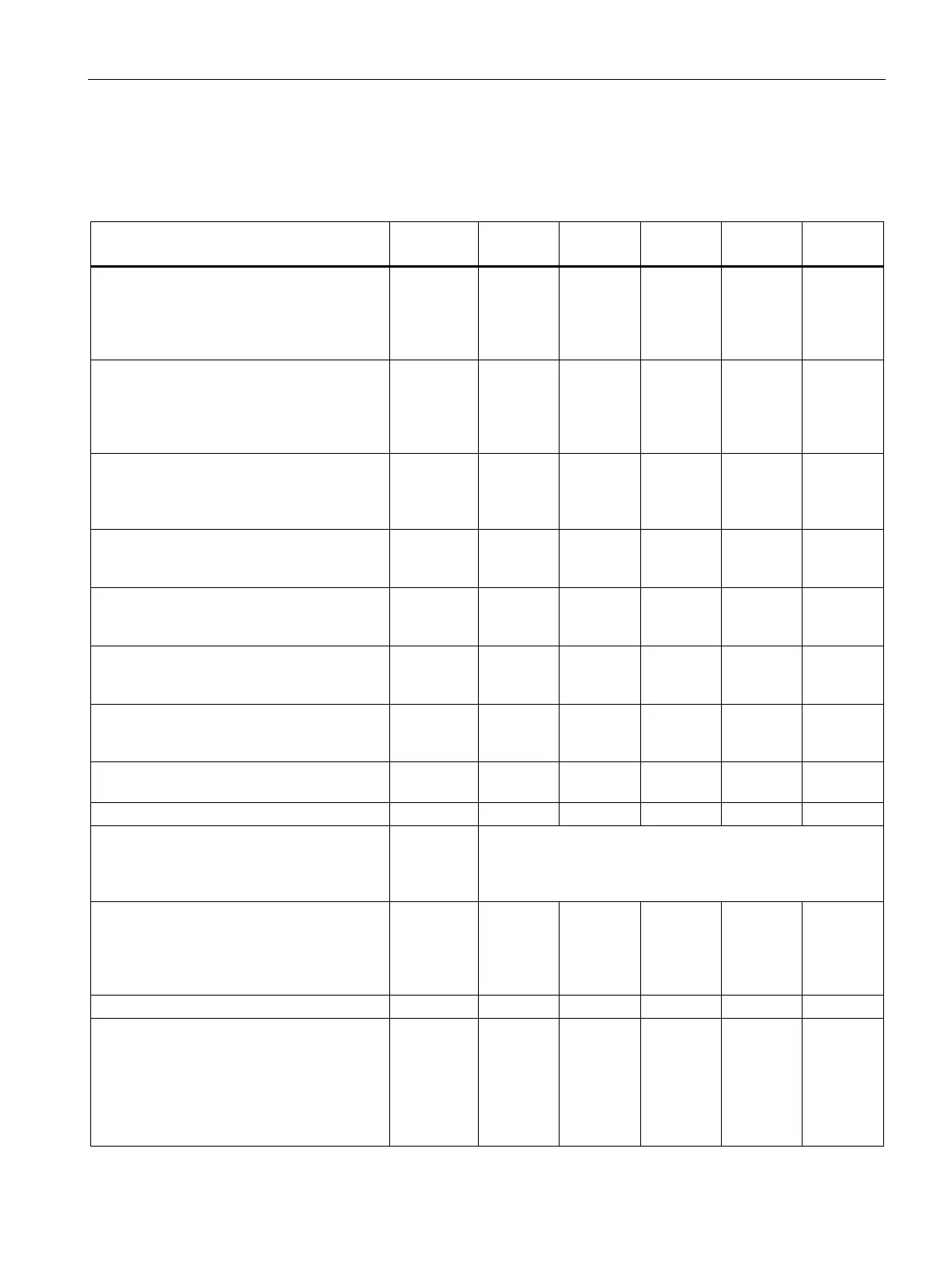
Table 5- 19 Technical specifications for Smart Line Modules, 380 to 480 V 3 ph. AC
- attached to Line Connection Module on
right side
- attached to Line Connection Module on left
--
--
--
--
...-1BU3
...-1CU3
...-3BU3
...-3CU3
...-7BU3
...-7CU3
- for I
N DC
(50 Hz 400 V)
- for I
H DC
(50 Hz 400 V)
- for I
N DC
(60 Hz 460 V)
- for I
H DC
(60 Hz 460 V)
kW
kW
HP
250
235
395
355
315
545
500
450
770
630
555
970
800
730
1230
- Rated current I
N DC
- Base load current I
H DC
1)
max DC
A
A
550
490
730
650
1050
934
1300
1157
1700
1513
- Rated current I
N E
A
463
614
883
1093
1430
- Auxiliary supply 24 V DC
2)
A
1.35
1.35
1.4
1.5
1.7
- Smart Line Module
µF
8400
12000
16800
18900
28800
3)
- at 50 Hz 400 V
kW
3.7
4.7
7.1
11.0
11.5
cfm
3
763
763
1653
2288
2288
Sound pressure level L
pA
(1 m) at 50/60 Hz
- Busbar cross-section
- Max. conductor cross-section (IEC)
- Max. conductor cross-section (NEC, CEC)
mm
2
mm
2
PE busbar
600
240
4)
- Shielded
- Unshielded
- Shielded
ft
ft
m
13200
19980
4000
13200
19980
4000
15840
23800
4800
15840
23800
4800
15840
23800
4800
Degree of protection (standard model)
(standard model, IP20)
- width
- height
5)
- depth
- width
- height
5)
inch
inch
inch
mm
mm
15.8
86.6
23.6
400
2200
15.8
86.6
23.6
400
2200
23.6
86.6
23.6
600
2200
31.6
86.6
23.6
800
2200
31.6
86.6
23.6
800
2200

 Loading...


