Options
8.22 K95, CU320-2 PN Control Unit
Cabinet Modules NEMA
434 Manual, 04/2014, A5E03586450A
Note
Connection cables
The PROFINET interfaces support Auto MDI(X). It is therefore possible to use both crossed
and uncrossed cables to connect the devices.
For diagnostic purposes, the two PROFINET interfaces are each equipped with a green and
a yellow LED. These LEDs indicate the following status information:
Table 8- 38 LED states of the X150 P1/P2 PROFINET interface
Link port
Green Continuous
10 or 100 Mbit link available
Activity port
Yellow Flashing
Data is being received or sent at port x
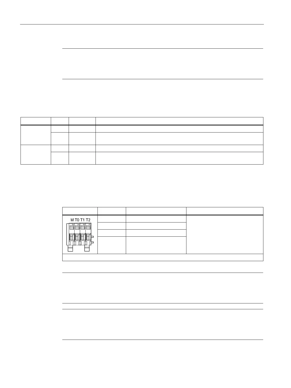
T0, T1, T2: Measuring sockets
Table 8- 39 Measuring sockets T0, T1, T2
Voltage: 0 ... 5 V
Resolution: 8 bits
Load current: max. 3 mA
Continued-short-circuit-proof
The reference potential is terminal M
M Ground
PCB plug connector from Phoenix Contact, type: ZEC 1.0/ 4-ST-3.5 C1 R1.4, order number: 1893708
Note
Cable cross-section
The measuring socket contacts are only suita
ble for cable cross-sections of 0.2 mm
2
to
mm
2
.
Note
Use of the measuring socket contacts
The measuring socket contacts are used to support commissioning and diagnostics. It must
not be connected for normal operation.

 Loading...


