Cabinet Modules
5.7 Auxiliary Power Supply Modules
Cabinet Modules NEMA
244 Manual, 04/2014, A5E03586450A
Adaptation of the circuit breaker (-Q2) for transformer (-T2)
For the protection of the transformer (-T2), a circuit breaker (-Q2) is installed before the
transformer.
The circuit breakers for the line supply are factory set in the voltage range from 500 to 690 V.
The circuit breaker must be adapted at the plant for supply voltages in the range from 380 V
to 480 V.
Adapting the circuit breaker
If the circuit breaker for a line supply in the voltage range from 380 to 480 V is not adapted
at the plant, the circuit breaker could trip inadvertently in the low voltage range from 380 to
480 V.
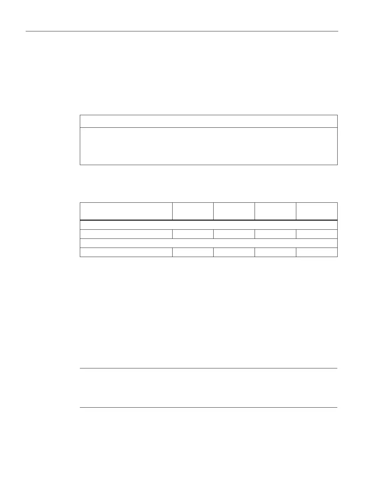
Table 5- 42 Overview of the settings of the circuit-breaker (-Q2) for the transformer (-T2) in the auxil-
iary power supply module
Auxiliary Power Supply Module
Order no. 6SL3700-
Voltage range 380 to 480 V 3 ph. AC
Voltage range 500 to 690 V 3 ph. AC (factory setting)
Auxiliary power supply system
Description
The auxiliary power supply system is used to distribute the available voltages (line voltage
for device fans, 230 V 2 ph. AC and 24 V DC). The table below shows an overview of the
connected voltages and associated fuses for the auxiliary power supply system in the
Auxiliary Power Supply Module. The 24 V DC voltage is provided directly from the SITOP
power supply and is not protected separately by a fuse. The 24 V DC power supply itself is
current-limited and short-circuit-proof at the output.
Note
The 24 V DC voltage is only available via the auxiliary power supply system.
The assignment of the auxiliary power module is described in the section "Electrical
installation", section "Connections/auxiliary power supply system".

 Loading...


