Cabinet Modules
5.1 Line Connection Modules
Cabinet Modules NEMA
132 Manual, 04/2014, A5E03586450A
Power is fed to the drive assembly via Line Modules, which generate a DC voltage from the
line voltage and, therefore, supply energy to the Motor Modules connected to the DC link.
They are suitable for connection to systems grounded at the star point (TN, TT) and
ungrounded systems (IT). The Line Modules are connected to the incoming supply via Line
Connection Modules and are equipped with a radio interference suppression filter in
accordance with IEC 61800-3 of category C3 as a standard feature.
Line Connection Modules contain the line-side infeed with main breaker and fuse switch
disconnector or circuit breaker and provide the connection between the plant power system
and the Line Modules.
Line Connection Modules are available for the following voltages and currents:
Rated infeed/regenerative feedback current
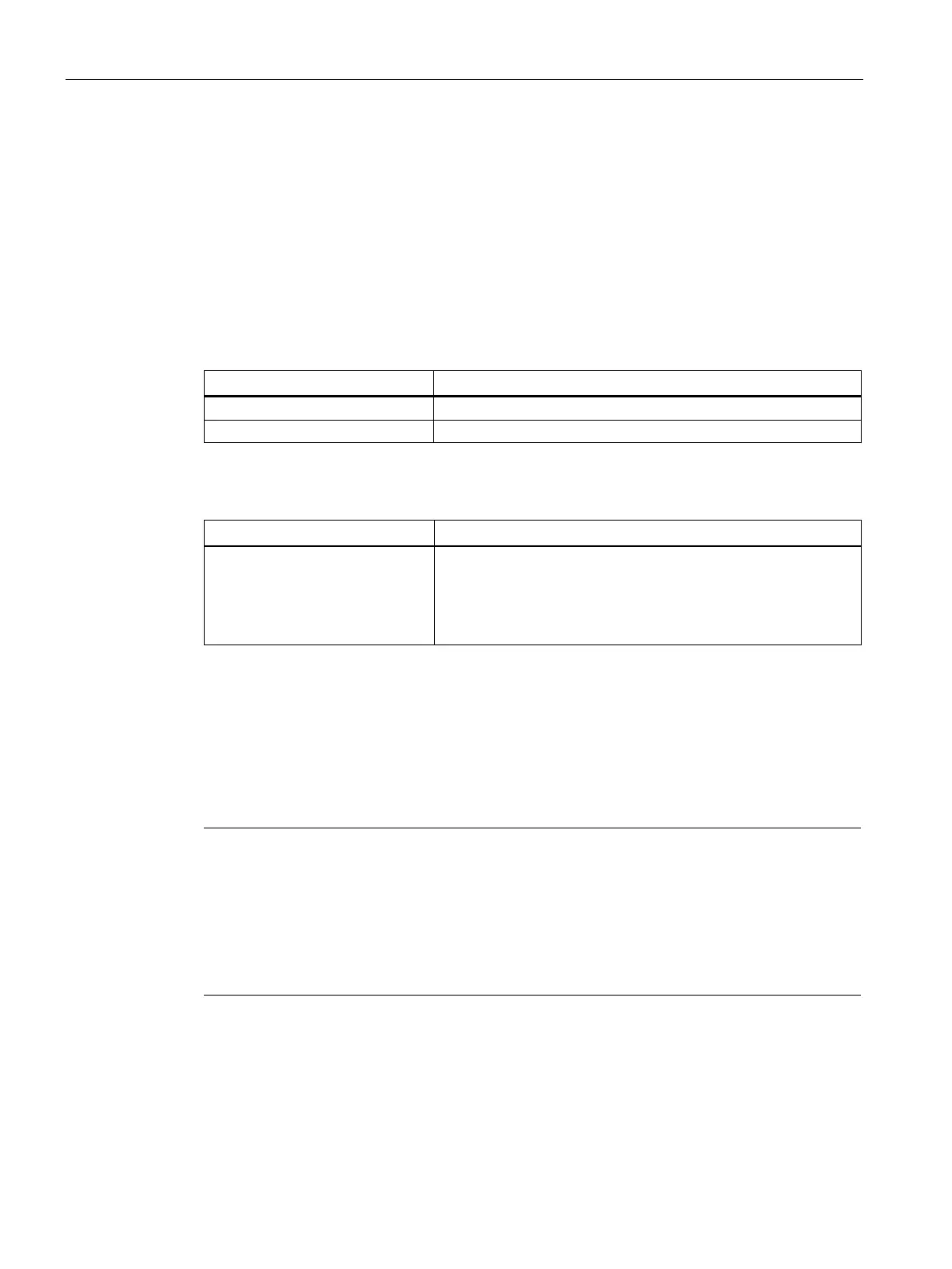
Table 5- 1 X1 terminals for the line supply
U1/L1, V1/L2, W1/L3
3 ph. AC power input
Voltage:
380 –10 % to 480 V +10 % 3 ph. AC (-15 % < 1 min)
500 –10 % to 690 +10 % V 3 ph. AC (-15 % < 1 min)
Frequency:
Depending on the input current, the following designs are used:
● ≤ 800 A: Main switch with fuse switch disconnector
● > 800 A: Circuit breaker, type 3WL, with option L25 as circuit breaker with current limiter
(3VL) and series-connected fuses
Note
Additional information
The configuration examples of the i
ndividual Line Connection Modules are used to illustrate
the positioning of the factory
-fitted components. They show the maximum possible
configuration of the modules, which contain all options that can be ordered.
Refer to the layout diagrams (AO) on the
customer DVD for the precise order-specific
positioning of the components.

 Loading...


