Electrical installation
4.5 Connections
Cabinet Modules NEMA
Manual, 04/2014, A5E03586450A
95
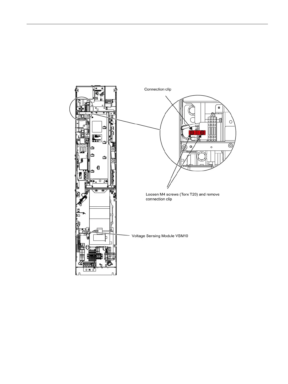
When the unit is operated on an ungrounded system (IT system), the connection clip to the
interference suppression capacitor must be removed.
With frame sizes HX and JX, you must remove the left-hand fan before you remove the
connection clip (see section "Replacing components").
Figure 4-16 Removing the connection clip to the basic interference suppression module in the Smart
Line Module for frame size GX

 Loading...


