3. Part of activities independent of serial number 6 - 9
Siemens AG SPR2-230.814.01 Page 9 of 42 SIREMOBIL Iso-C 3D
Medical Solutions Rev. 05 08.04 CS PS 24
Installation of the support arm on the monitor trolley
• Open the rear cover of the support arm base on the TFT display.
• Route the free cable ends of the new power line cables (included in the attachment of the
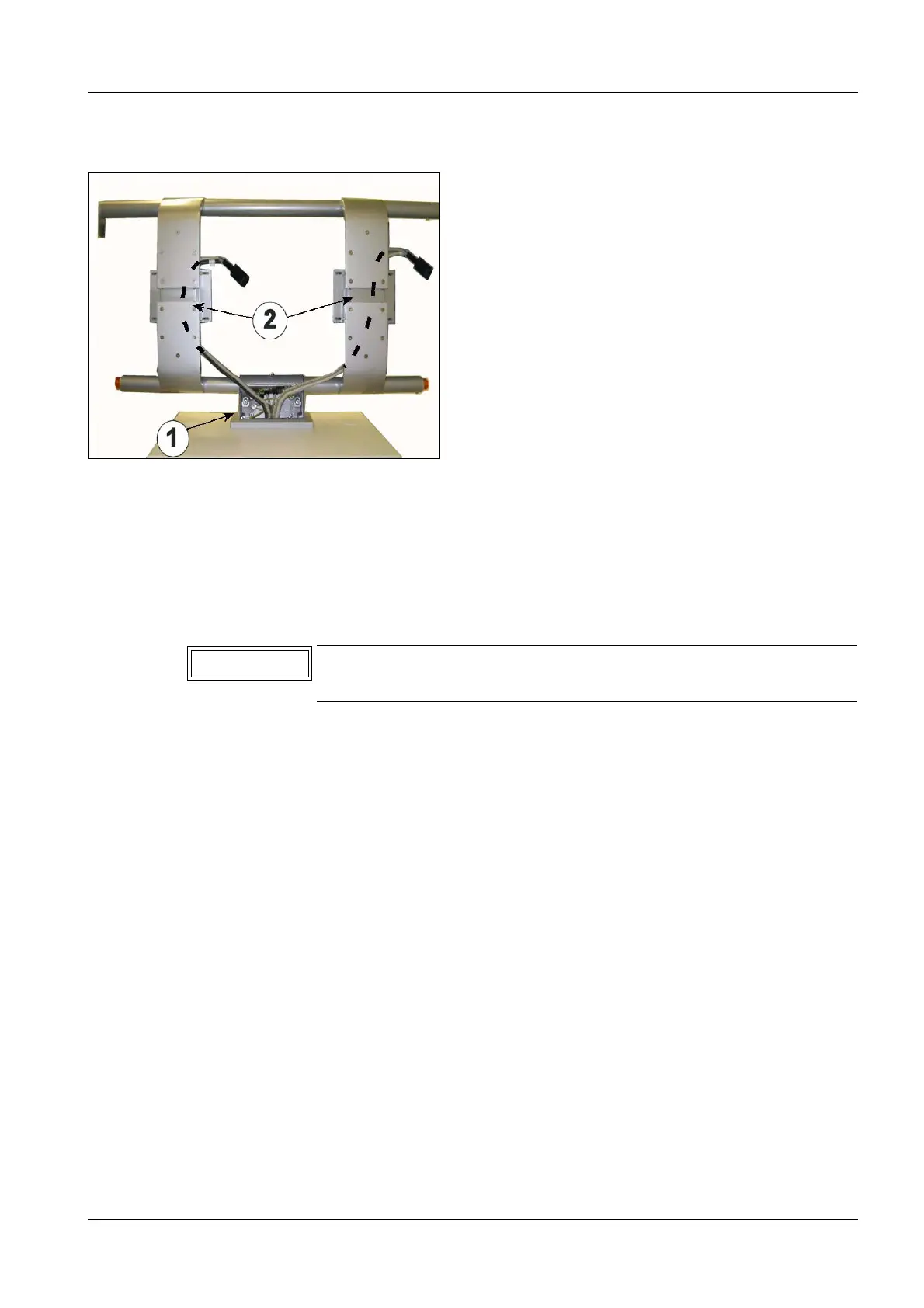
TFT Display) downwards through the support arm holder (2/Fig. 24), through the center
cable bush of the monitor trolley and through the lateral rail to the ON/OFF assembly
(Fig. 23) and connect them to the terminal blocks:
- Connect the brown cable ends to terminal block X2.1
- Connect the blue cable ends to terminla block X2.2
- Connect the protective ground cable ends (ye/gn) to the protective conductor bars
(1/Fig.23).
• Route the cable ends of the video cables upwards through the support arm base
(1/Fig.24) and further through the support arm holder (2/Fig. 24).
• Place the support arm base above the center cable bush (Fig.24).
• Starting with the logbook compartment, tighten the screws of the support arm base on
the monitor trolley. Use 4 Allen screws M6 x 20, 4 lock washers and 4 plate washers for
this (Fig. 24).
Fig. 24 Installation of the support arm
The new poer line cables have a length of approx. 2.6m and are
equiped with a straight femal connector on one cable end.
Mark for the keyboard tray
NOTE

 Loading...


