SIREMOBIL Iso-C 3D SPR2-230.814.01 Page 8 of 42 Siemens AG
Rev. 05 08.04 CS PS 24 Medical Solutions
6 - 8 3. Part of activities independent of serial number
Installation of the video and power line cables in the monitor trolley
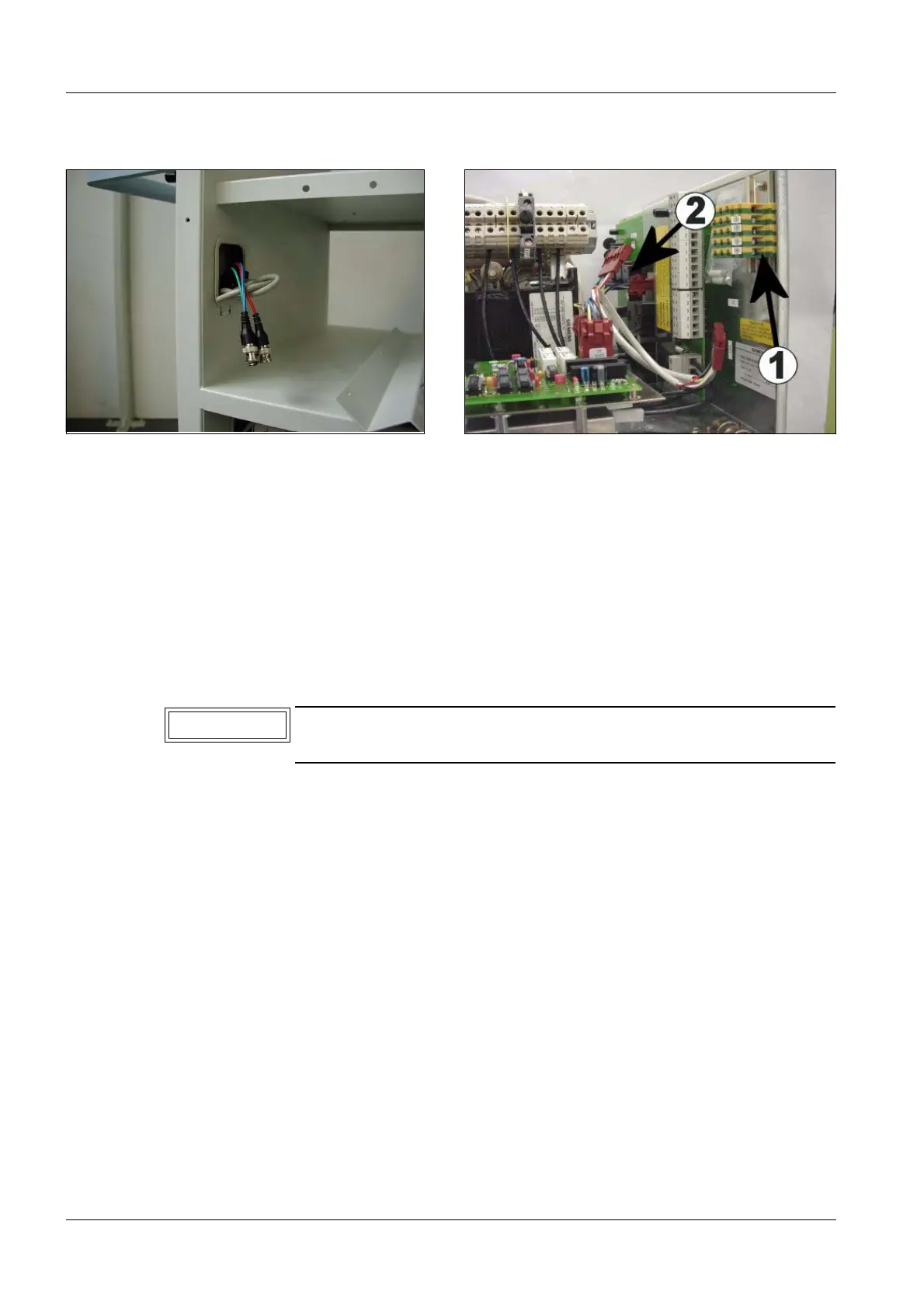
• Route the video cable included in the system cabling set 71 39 855 for the TFT display
on the right-hand side (3 BNC connectors --- 3 BNC connectors) from the logbook com-
partment of the monitor trolley through the center cable bush.
• Route the other end of the video cable in the lateral rails of the monitor trolley to the low-
er compartment of the monitor trolley (video-printer compartment), as shown in Fig. 22.
• Route the second video cable (included in the set attachment of the TFT monitor) of the
left TFT display (length approx. 2.1 m) through the center cable bush of the monitor trol-
ley and through the lateral rail to MEMOSCOPE, socket Out 1. Then, plug the cable in
and lock it.
Fig. 22 Video cable reference / 3D display Fig. 23 Video cable Reference / 3D display
On one end of the cable, the outer sheath of the new video cable is
removed. Connect this cable end to the TFT display.
NOTE

 Loading...


