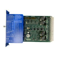
Internal circuit diagram
.
;
;
0004444
/
000).).).).
9
Figure 5-14 4F‑DO internal circuit diagram
Terminal designations of the expansion module 4F‑DO
Terminal Meaning Description
Q1, Q2, Q3,
Q4
Safety-related semiconduc‐
tor outputs
Two-channel semiconductor outputs for connecting ac‐
tuators
L+ Power supply 24 V DC
M, 1M, 2M Ground Ground to 24 V DC
Interfaces of the expansion module 4F-DO
Interface Meaning Description
X1 System interface Connection of central unit/expansion module
X2 System interface Connection of expansion module
Displays of the expansion module 4F-DO
Element Meaning
SF/Q1 Group error / state of the semiconductor outputs
Q2, Q3, Q4 State of the semiconductor outputs
Connecting inputs and outputs
You will nd further information on connecting inputs and outputs in Chapter "Wiring rules for
inputs and outputs (Page 134)."
Description of the hardware
5.1 Description of the individual modules
SIRIUS 3RK3 Modular Safety System
Equipment Manual, 07/2020, NEB926253002000/RS-AC/006 107

 Loading...


