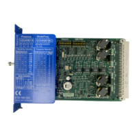
Terminal names of the 3RK3 Basic central unit
Terminal Meaning Description
T1 Test output for inputs IN1,
IN3, IN5, IN7
• Test outputs with dierent test signals
• Connection for sensor contacts for detecting cross-
circuits
T2 Test output for inputs IN2,
IN4, IN6, IN8
IN1 ... IN8 Safety-related sensor inputs Terminal for safety sensors
Combinations for two-channel connection:
• IN1 with IN2
• IN3 with IN4
• IN5 with IN6
• IN7 with IN8
Q1.1, Q1.2 Safety-related relay output Isolated two-channel output for connecting actuators
Q2 Safety-related semiconduc‐
tor output
Two-channel output for connecting actuators
L+ Power supply 24 V DC
M Ground Ground to 24 V DC
FE Functional ground Shielding, equipotential bonding
Interfaces of the 3RK3 Basic central unit
Interface Meaning Description
X1 Device interface Connection of PC or programming device, interface mod‐
ule, diagnostics display
X2 System interface Interface for connecting expansion modules (e.g. I/O
modules)
X3 External memory module Slot for external memory module with parameterization
data
The memory module is sealable with the 3RK3 central
unit or the control cabinet.
Operator controls of the 3RK3 Basic central unit
Element Meaning Description
RESET button
• Error acknowledgment
• Factory setting
• Conrm the acknowledgeable errors with this button.
• Refer to Chapter "Restoring factory settings
(Page 347)"
Displays of the 3RK3 Basic central unit
Element Meaning
DEVICE Device status
SF Group error
Description of the hardware
5.1 Description of the individual modules
SIRIUS 3RK3 Modular Safety System
78 Equipment Manual, 07/2020, NEB926253002000/RS-AC/006

 Loading...


