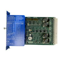
Structure of the 3RK3 Advanced central unit
Front view No. Meaning
7,1,1,1,1$6L
7,1,1,1,1$6L
444/0)(
;;
'(9,&(
6)
5(6(7
,1
066$GYDQFHG
$6L
7($&+
24V
DC
,1,1,14
,1,1,1,14
3RK3131-1AC10
① Removable terminal block D
② Removable terminal block C
③ Connection for expansion module (X2)
④ RESET button
⑤ Removable terminal block A
⑥ External memory module (X3; sealable)
⑦ Label
⑧ Display LEDs
⑨ Connection of PC or programming device,
interface module, diagnostics display (X1)
Internal circuit diagram
/RJLF
.
$6L$6L
;
;
)(440
4,1,1,1,17,1,1,17,1/
).).0
).9
Figure 5-5 MSS 3RK3 Advanced internal circuit diagram
Terminal names of the 3RK3 Advanced central unit
Terminal Meaning Explanation
T1 Test output for inputs IN1,
IN3, IN5, IN7
• Test outputs with dierent test signals
• Connection for sensor contacts for detecting cross-
circuits
T2 Test output for inputs IN2,
IN4, IN6, IN8
Description of the hardware
5.1 Description of the individual modules
SIRIUS 3RK3 Modular Safety System
82 Equipment Manual, 07/2020, NEB926253002000/RS-AC/006

 Loading...


