EasyManuals Logo

Simplex 4100 Installation Manual

Simplex 4100
97 pages
To Next Page IconTo Next Page
To Previous Page IconTo Previous Page
Page #22 background imageLoading...
Page #22 background image
Page 14 SIMPLEX 4100 EWIS
INSTALLATION MANUAL
Document No.: 4100-M011 March 1998 Issue 1.0
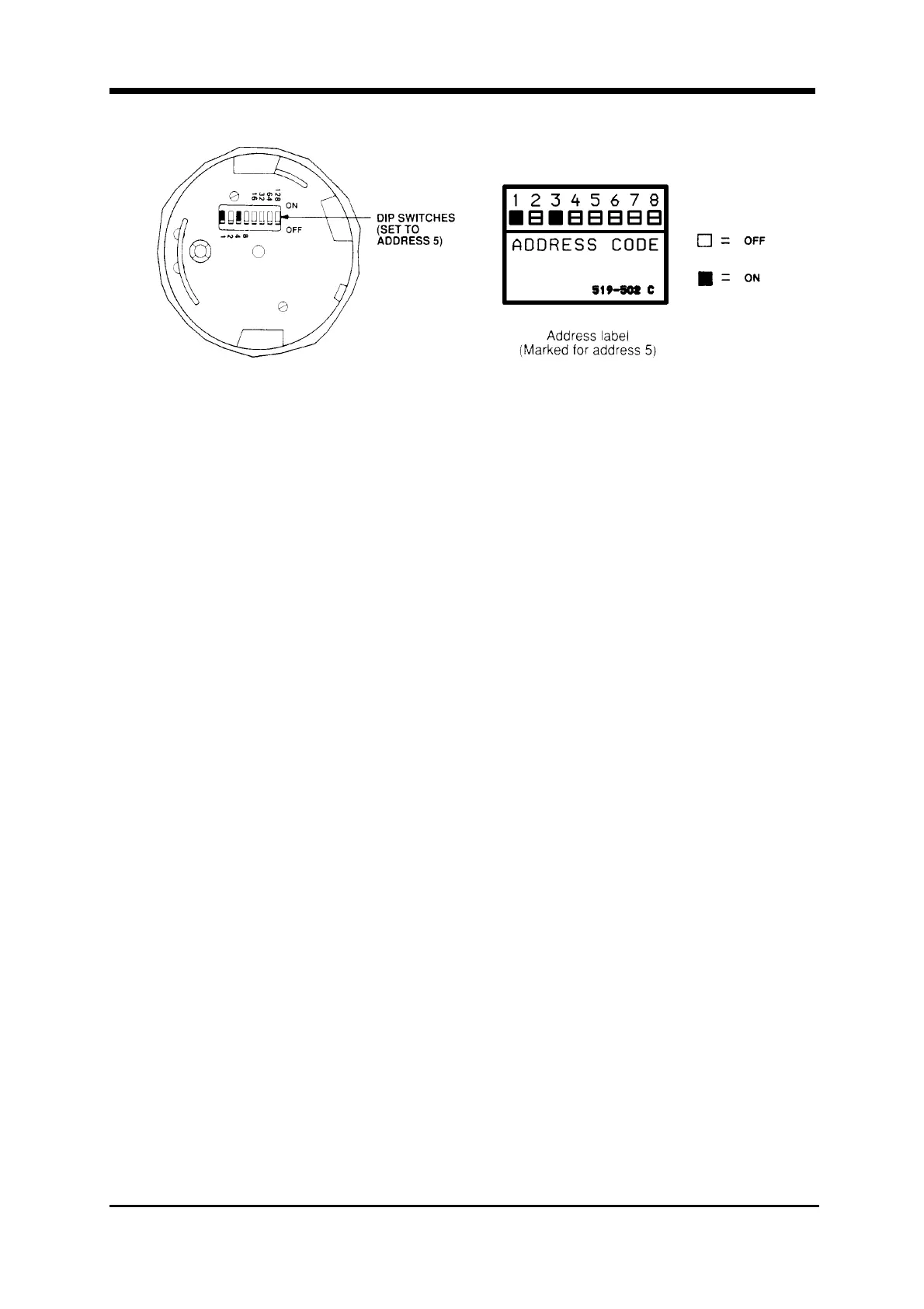
Figure 8 Location of DIP Switches
on Typical Device
Figure 9 Device Address Label
2.5 BAY DOOR OPTION.
See Figure 10
a. (If applicable) Mark the top of the ribbon cable. Then pull the cable
straight out of its connector.
b. Remove the hair-pin cotter pins (item 1) from the upper clevis pins
(item 2). Then push the clevis pins inward and lower the door.
c. Free the lower end of the retainer cable (item 3) by removing the screw
and washer (items 4 and 5).
d. Remove the hair-pin cotter pins (item 6) from the lower clevis pins
(item 7). Then push the clevis pins inward and remove the door.
e. Store the door and its hardware in a safe, clean and dry place until all
wires are terminated in the 4100 panel.

Table of Contents

Other manuals for Simplex 4100

Questions and Answers:

Question and Answer IconNeed help?

Do you have a question about the Simplex 4100 and is the answer not in the manual?

Simplex 4100 Specifications

General IconGeneral
TypeFire Alarm Control Panel
ManufacturerSimplex
Model4100
Network CapabilityYes
AddressableYes
Power Supply120/240 VAC, 50/60 Hz
DisplayLCD
Annunciator SupportYes
Battery BackupYes
Releasing CapabilityYes
Max DevicesDepends on configuration
Max Notification Appliance Circuits (NAC)Varies with configuration
Max Releasing CircuitsVaries with configuration
Max Remote AnnunciatorsVaries with configuration
Communication PortsMultiple
Operating Temperature32°F to 120°F (0°C to 49°C)
Humidity RangeUp to 93% RH, non-condensing
NAC Outputs4 (expandable)
NetworkingYes

Related product manuals