EasyManuals Logo

Simplex 4100 Installation Manual

Simplex 4100
97 pages
To Next Page IconTo Next Page
To Previous Page IconTo Previous Page
Page #56 background imageLoading...
Page #56 background image
Page 48 SIMPLEX 4100 EWIS
INSTALLATION MANUAL
Document No.: 4100-M011 March 1998 Issue 1.0
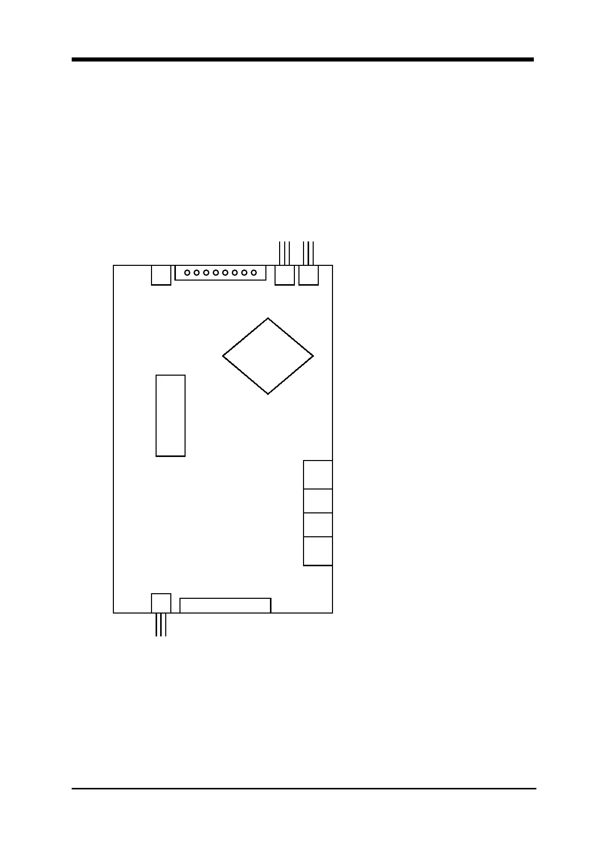
3.8.1 Network WIP Phone Termination – Master Node
The WIP Master Phone is terminated on connector P6. Only use approved master
phone part number 2084-9106.
The next node in the network is terminated on connector P4.
The last node in the network is terminated on connector P3.
Figure 20 WIP Network Master Node Phone Terminations
The Master Phone Handset terminations are on terminals labelled 1 & 2.
The positive line on terminal 1 and the negative line on terminal 2.
IC
Power
&
Communication
connections
P5 P3 P4TB1
4100-0205
P6
Master
Phone
Handset
Not Used
Not Used
1 2 3 4 5 6 7 8
To First Node
in Network
From Last Node
in Network

Table of Contents

Other manuals for Simplex 4100

Questions and Answers:

Question and Answer IconNeed help?

Do you have a question about the Simplex 4100 and is the answer not in the manual?

Simplex 4100 Specifications

General IconGeneral
TypeFire Alarm Control Panel
ManufacturerSimplex
Model4100
Network CapabilityYes
AddressableYes
Power Supply120/240 VAC, 50/60 Hz
DisplayLCD
Annunciator SupportYes
Battery BackupYes
Releasing CapabilityYes
Max DevicesDepends on configuration
Max Notification Appliance Circuits (NAC)Varies with configuration
Max Releasing CircuitsVaries with configuration
Max Remote AnnunciatorsVaries with configuration
Communication PortsMultiple
Operating Temperature32°F to 120°F (0°C to 49°C)
Humidity RangeUp to 93% RH, non-condensing
NAC Outputs4 (expandable)
NetworkingYes

Related product manuals