6 Removing the Left Enclosure Lid
SMA Solar Technology AG
Replacement ManualSTPxxx-60-DC-SPD-RM-xx-1116
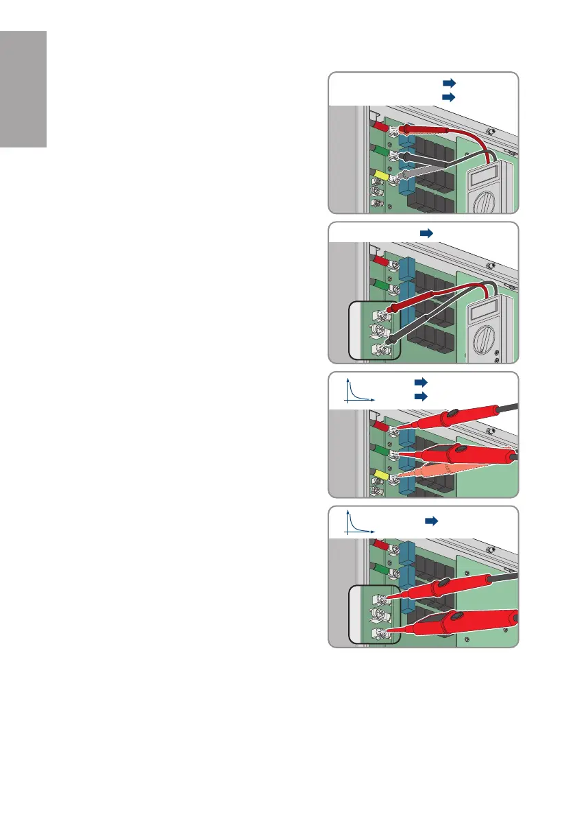
4. Ensure that the voltage on the capacitors between T
(red) and S (green) and T (red) and R (yellow) is
less than 60V within the DC measuring range.
T
S
R
T S < 60 V
T R < 60 V
5. Ensure that the voltage on the DC link between
BUS+ and BUS- is less than 60V in the DC
measuring range.
6. Actively discharge capacitors: For this purpose use,
for example, a 2-pole voltage detector that does not
have its own voltage source. Measure with the
voltage detector between T (red) and S (green) and
T (red) and R (yellow) until a value of less than 5 V
in the measuring range is displayed.
T
S
R
T S < 5 V
T R < 5 V
U
t
7. Actively discharge DC link: For this purpose use, for
example, a 2-pole voltage detector that does not
have its own voltage source. Measure with the
voltage detector between BUS+ and BUS- until a
value of less than 5 V in the DC measuring range is
displayed.
ENGLISH