8 Installing the DC SPD
SMA Solar Technology AG
Replacement ManualSTPxxx-60-DC-SPD-RM-xx-1118
8 Installing the DC SPD
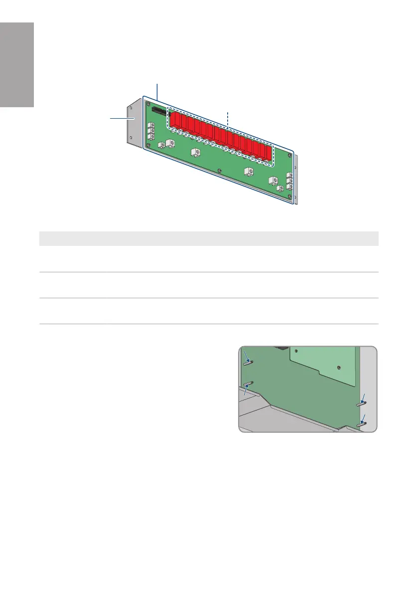
Figure 2 : DC SPD handling area
Position Designation
A Area that can be touched without consequence. This area can be used as a
holding point during mounting.
B Area that has to be handled with great care. This area can be used as a hold-
ing point during mounting.
C Area that may be used as holding point. The color of the components may dif-
fer depending on the assembly.
Procedure:
1. Only for 202086-00.01 - SPD Type 1+2 board for
STP 110-6x (retrofit kit) und 202757-00.01 - SPD
Type 1+2 board for STP 110-6x (spare part):
Remove the 4 PCB brackets (SW4) and insert the
new PCB brackets included in the scope of delivery
(AF4, torque: 1.5±0.1Nm)
2. Only for 123263-00.01 - Spare Part DC-SPD board STP 110-60: Ensure the 4 PCB brackets
are securely connected.
3. Align new DC SPD and insert it into inverter. If the PCB brackets rotate when the DC-SPD is
inserted, use a box wrench to fix the PCB brackets. Ensure that the ribbon cable hangs over
the top edge of the DC-SPD.
ENGLISH