121
Information Wiring Diagrams
9.6 Wiring Diagrams
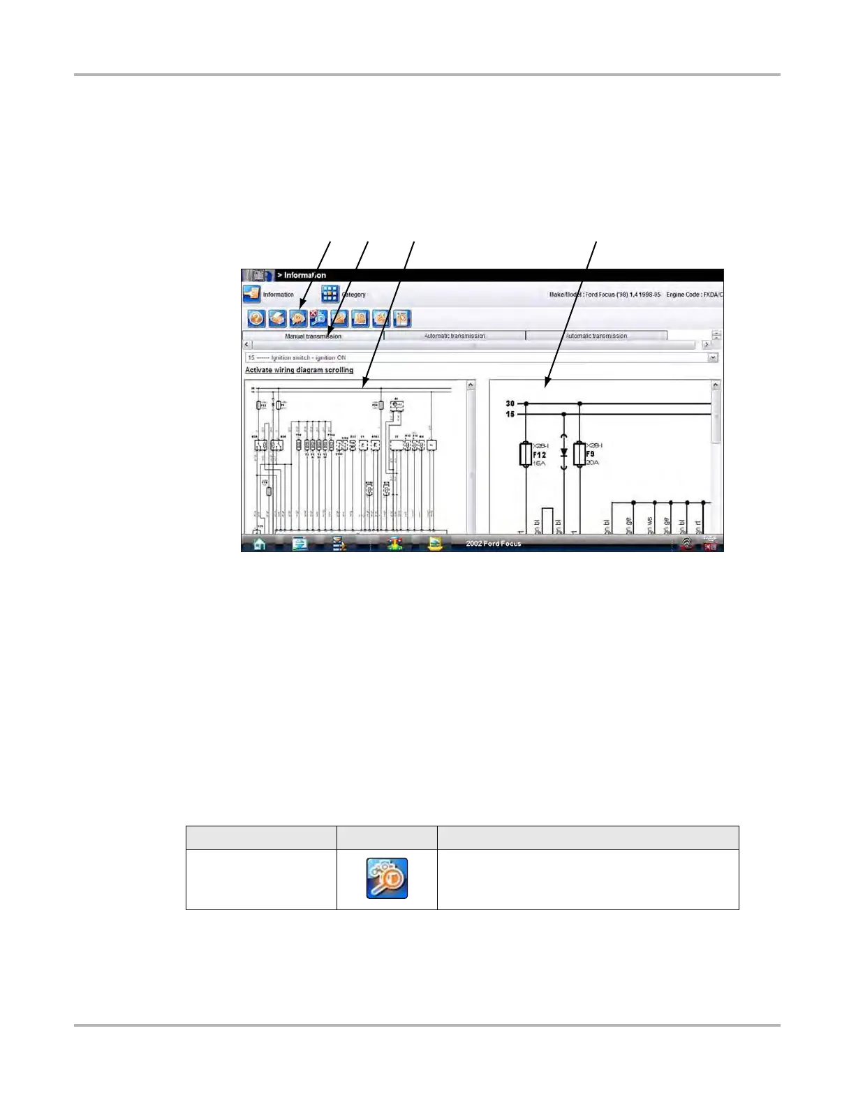
This home page selection contains system wiring diagrams for the identified test vehicle, the
number of diagrams available varies by year and model. Selecting the Wiring Diagrams icon
opens a data category menu. Select a menu item with the stylus to open the wiring diagram. A
typical wiring diagram screen is shown in Figure 9-10.
1— Toolbar
2— Component Selection Menu
3— Full-width Window
4— Magnified Window
Figure 9-10 Sample wiring diagram screen
9.6.1 Toolbar
Most of the toolbar icon are the same as for Engine management Component Testing, see
“Toolbar” on page 116 for descriptions. However, there are some icons that only appear on wiring
diagrams. These are explained in the table below.
Table 9-3 Information icon descriptions
Name Icon Description
ECM Harness Connector
Opens an ECM harness connector diagram in a
separate window. Only the connector displays, pin
data in not shown.