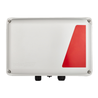
2.
LoosenthescrewsonthefrontcoveroftheStorEdgeConnectionUnitusingthesuppliedAllenkey,as
shownbelow:
Figure 10: Opening the StorEdge Connection Unit cover
3. RemovetheStorEdgeConnectionUnitcover.
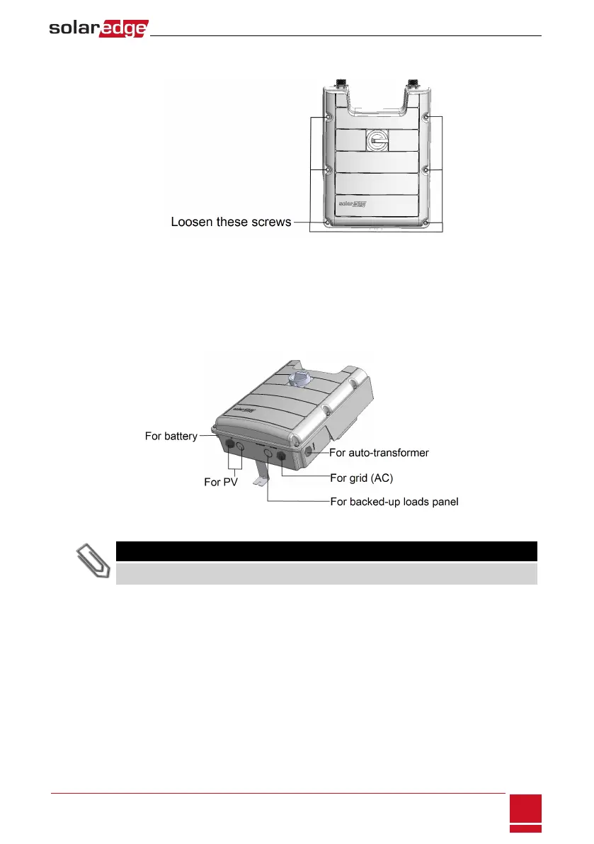
4.
Opentherequiredconduitknockoutsaccordingtotheconduitsusedintheinstallation(refertothe
figurebelowforrequiredknockouts;someoftheknockoutsmayalreadybeopenbutsealed):The
knockoutsarelocatedatthebottomoftheenclosure,eachwithtwosizes:¾''and1''.Openthe
requiredknockouts,takingcarenottointerferewithanyoftheinternalcomponents.AUnibitdrill
maybeused.
Figure 11: StorEdge Connection Unit knockouts
NOTE
Unused conduit openings and glands should be sealed with appropriate seals.
Chapter 3: Installing the Inverter
SolarEdge-StorEdge Installation Guide MAN-01-00262-1.0
21