8.
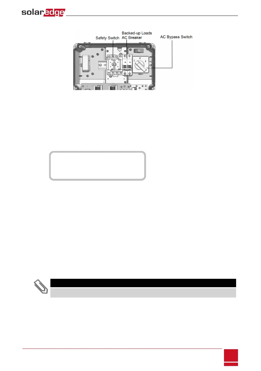
Makesurethebacked-uploadsACbreakerisUP.
Figure 29: StorEdge Connection Unit
9. ClosetheStorEdgeConnectionUnitcover:Attachthecoverandsecureitbytighteningthesixscrews
withatorqueof1.2N*m/0.9ft.*lb.
10. Ensureproperconduitsealing;inspecttheentireconduitrunandusestandardconduitsealantsto
avoidwaterpenetration.
11.
TurnONtheStorEdgeConnectionUnitswitch.IfanadditionalexternalDCswitchisinstalledbetween
thepoweroptimizers/batteryandtheinverter(s)thenturnitON.
AstatusscreensimilartothefollowingappearsontheLCDpanel:
V a c [ V ] V d c [ V ] P a c [ w ]
2 4 0 . 7 1 4 . 1 0 . 0
P _ O K : 0 0 0 / 0 0 0 < S _ O K >
- - - - - - - - - - - - - - - O F F
12. VerifythatthefollowinginformationappearsontheLCDpanel:
l P_OK:Appearsonlyuponfirsttelemetryreceptionfromthepoweroptimizers.Indicates
connectiontothepoweroptimizersandthatatleastonepoweroptimizerissendingmonitoring
data.IfP_OKdoesnotappear,checkthepoweroptimizer,stringandDCinputconnections.
l 000/000:Appearsonlyuponfirsttelemetryreceptionfromthepoweroptimizers.Indicatesthe
numberofpoweroptimizersthathavebeenpairedtothisinverter.Atthisstage,thenumber
shouldbe000,sincenopoweroptimizershavebeenpaired.
l S_OK:theconnectiontotheSolarEdgemonitoringportalissuccessful(shouldappearonlyifthe
inverterisconnectedtotheserver).IfS_OKisnotdisplayedandtheinverterisconnectedtothe
server,referto"Troubleshooting"onpage79.
l Vac [V]:thegridACoutputvoltage.Verifythecorrectvalue.
l Vdc [V]:TheDCinputvoltageofthelongeststringconnectedtotheinverter.Thereshouldbea
safetyvoltageof1Vforeachpoweroptimizerinthestring.
NOTE
A measurement error on the inverter LCD of ±3 V is acceptable.
l Pac [w]:theACoutputpower(shouldbe0.0sincetheinverterisOFF).
l OFF:theinverterON/OFFswitchisintheOFFposition.
Chapter 8: Commissioning the Installation
SolarEdge-StorEdge Installation Guide MAN-01-00262-1.0
57
 Loading...


