6.
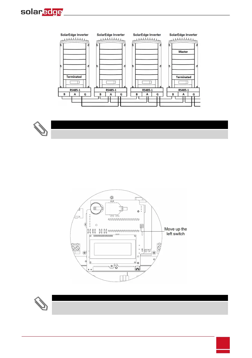
ForcreatinganRS485bus-connectallB,AandGpinsinallinverters.Thefollowingfigureshowsthis
connectionschema:
Figure 38: Connecting the inverters in a chain
NOTE
Do not cross-connect B, A and G wires. Do not insert wires into RS485- 2 pins.
7. Tightentheterminalblockscrews.
8. Checkthatthewiresarefullyinsertedandcannotbepulledouteasily.
9.
PushtheRS485terminalblockfirmlyallthewayintotheconnectorontherightsideofthe
communicationboard.
10.
TerminatethefirstandlastSolarEdgedevice(inverter/Controlandcommunicationgateway,etc.)in
thechainbyswitchingaterminationDIP-switchinsidetheinvertertoON(movetheswitchup).The
switchislocatedonthecommunicationboardandismarkedSW7.
Figure 39: RS485 termination switch
NOTE
Only the first and last SolarEdge devices in the chain should be terminated. The other inverters
in the chain should have the termination switch OFF (down position).
Chapter 10: Setting Up Communication to the Monitoring Portal
SolarEdge-StorEdge Installation Guide MAN-01-00262-1.0
77
 Loading...


