92
Electrical Connection
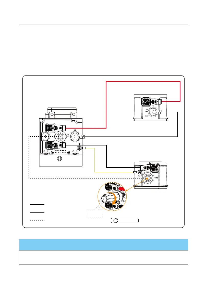
Step 3: Connect B+ of the BMS to B+ of the series box;
Connect B- of the BMS to B- of the series box;
Connect COM port of the BMS to COM port of the series box;
Connect HEAT port of the BMS to HEAT port of the series box;
Connect the grounding port of the BMS to the grounding port of the series box.
HEAT
Power cable (red)
Power cable (black)
Heater cable (HEAT port)
Communication cable (COM port)
Grounding cable
Left side of series box
Right side of series box
Right side of BMS
Rotation
wrench
Communication cable
Power cable
Heater cable
0.8-1.0 N·m
Grounding cable
Figure 7-9 Connecting cables
NOTICE!
• There are two terminals on both ends of the power cable;
• Both ends of the communication cable shall be closed by using a rotation wrench.

 Loading...


