73
Mechanical Installation
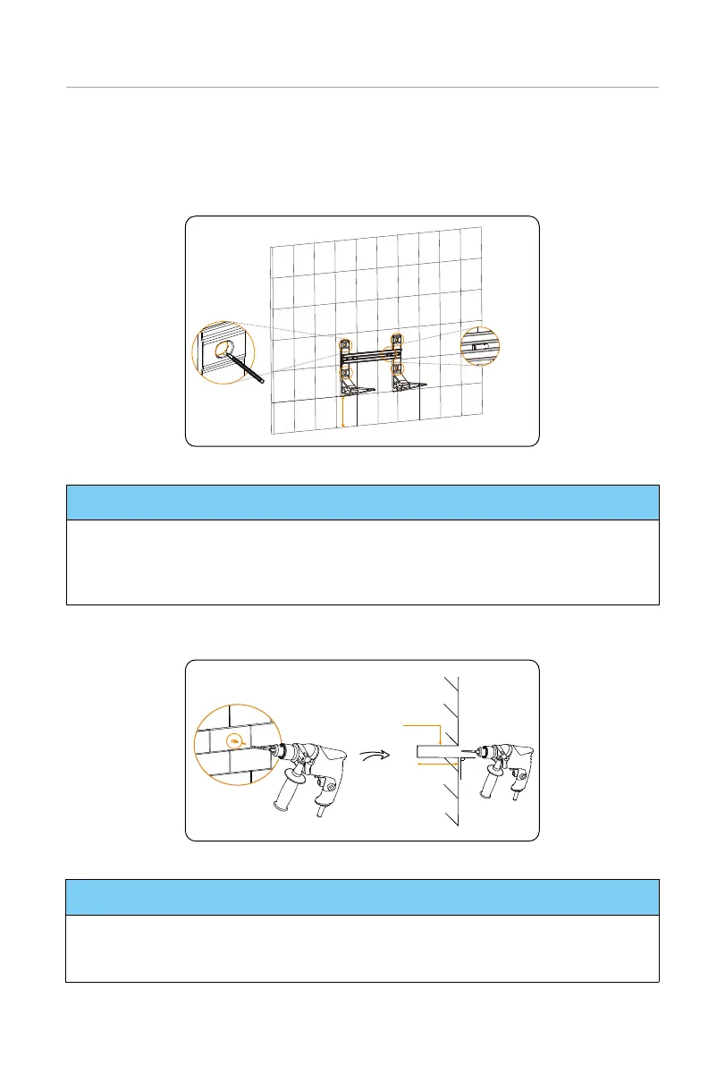
Step 3: Place the assembled base support and transverse plate on the wall, check the
cylindrical plastic bubble spirit level on the transverse plate. If the bubble isn't in
the centre, slightly bow it to the horizontal.
Then circle along the inner ring of the four holes.
cylindrical
plastic
bubble
spirit level
Ground
Figure 6-32 Drawing circles
NOTICE!
• The distance from the base support to the ground is decided according to the local
regulations. And it is also the distance from the base to the ground. For the safety
concerns, it is suggested that the height from the ground not be too high.
• Please leave enough distance to the ceiling to install the inverter.
Step 4: Remove the assembled base support and transverse plate, and then drill four
holes at a depth of at least 110 mm by using a drill (Ø15 mm).
Concrete Wall
90°
Ø15 mm drill
≥ 110 mm
Figure 6-33 Drilling holes
NOTICE!
• An electric drill dust collector is recommended.
• To prevent dust from being released into the hot plug when drilling holes, users may
use the package bag of the device or other materials to fully cover the base.

 Loading...


