78
Mechanical Installation
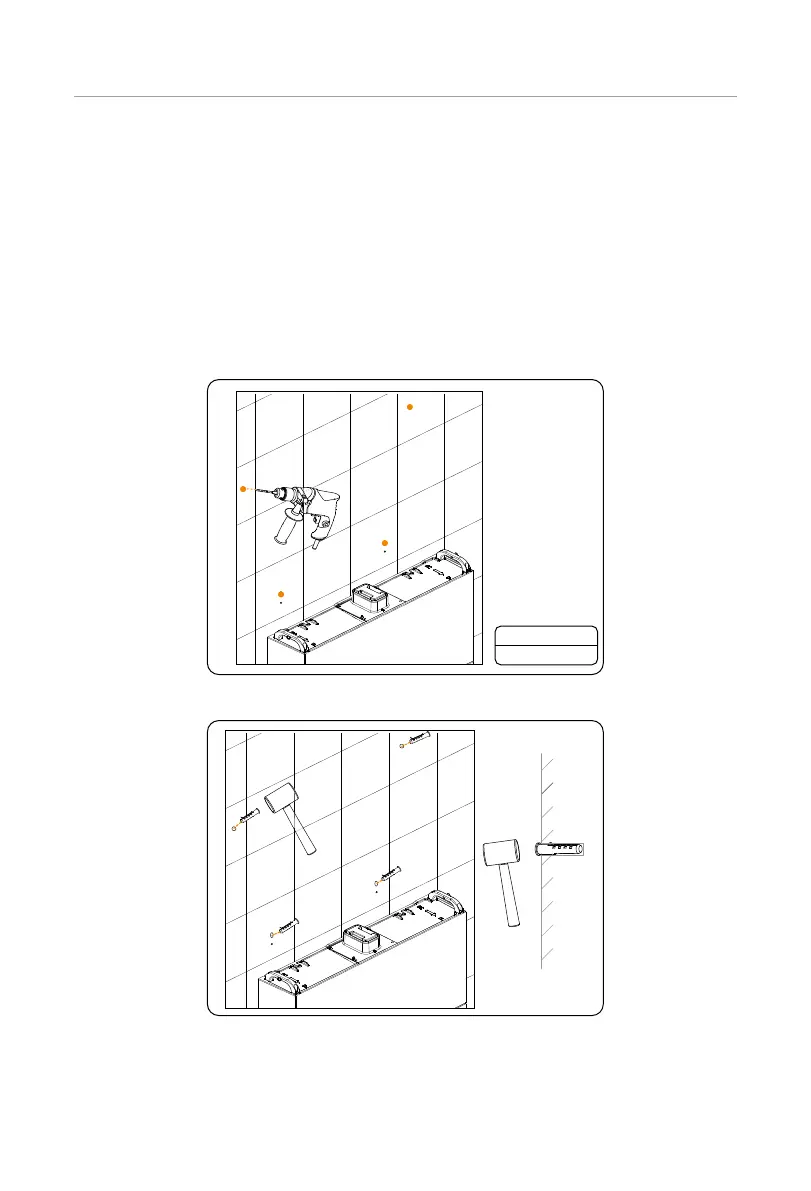
Step 11: Drill the holes for the BMS and the inverter and tighten them.
1. Remove the assembled brackets on the battery module, and then drill the four
holes at a depth of more than 60 mm in the concrete wall by using a drill (Ø10
mm);
2. Insert the expansion tubes into the four holes and knock them into the wall
with a rubber hammer;
3. Thread the screw through the assembled bracket and into the holes on the
battery module, and then tighten the screws. Thread the self-tapping screws
through a washer and then the assembled bracket, insert the screws into the
holes on the wall and tighten the screws.
Ø10 drill
Depth: >60 mm
Figure 6-43 Drilling holes
Figure 6-44 Knocking expansion tubes into the wall

 Loading...


