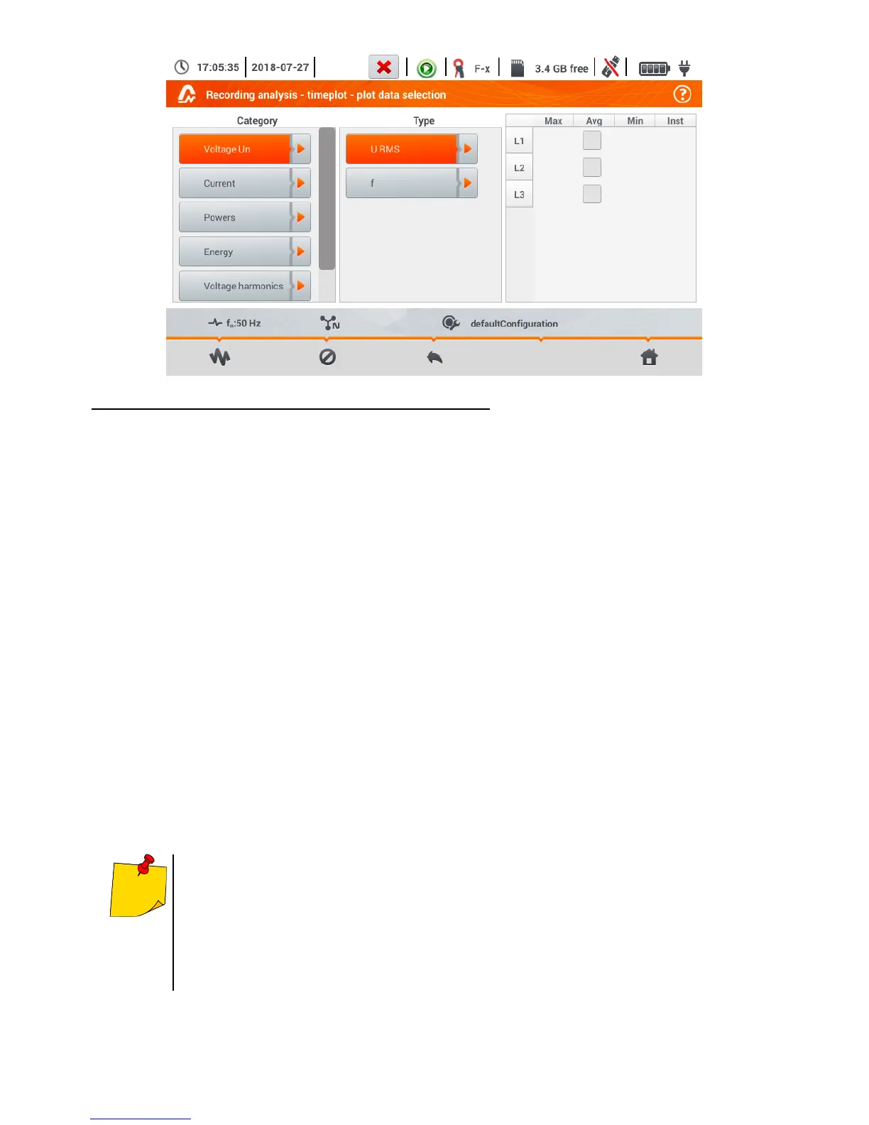
Available option (differing depending on the network layout)
Un voltage
o U RMS (effective voltage) – for phases L1, L2, L3 (A, B, C)
o U L-L (phase-to-phase voltage)
o f (frequency) – for phase L1 (A)
Current
o I RMS (effective current) – for phases L1, L2, L3 (A, B, C)
Power
o P (active power) – for phases L1, L2, L3 (A, B, C) and Σ sum
o Q1 (reactive power) – for phases L1, L2, L3 (A, B, C) and Σ sum
o Sn (distortion power) – for phases L1, L2, L3 (A, B, C) and Σ sum
o S (apparent power) – for phases L1, L2, L3 (A, B, C) and Σ sum
o cosφ – for phases L1, L2, L3 (A, B, C) and Σ sum
o PF (power factor) – for phases L1, L2, L3 (A, B, C) and Σ sum
Energies
o EP+ (active energy consumed from network) – for phases L1, L2, L3 (A, B, C) and Σ sum
o EP- (active energy supplied to network) – for phases L1, L2, L3 (A, B, C) and Σ sum
o EQ+ (reactive energy consumed from network) – for phases L1, L2, L3 (A, B, C) and Σ sum
o EQ- (reactive energy supplied to network) – for phases L1, L2, L3 (A, B, C) and Σ sum
o ES (apparent energy) – energy for phases L1, L2, L3 (A, B, C) and in total Σ
Harmonics U
o THD U (total harmonic distortion) – for phases L1, L2, L3 (A, B, C)
o U h1…U h40 (1…40. voltage harmonic) – for phases L1, L2, L3 (A, B, C)
In the window for selecting the parameters, only those parameters are displayed
which were recorded.
For better orientation, the fields with parameters selected for the chart, the fields of
category and type are surrounded by orange border, if they contain any selected pa-
rameters.
If you have already ticked four parameters, any attempt to select another will result
in displaying a message on limited number of parameters in the chart.