Transmitting clamps and measuring clamps should be attached to the tested earth elec-
trode at a distance of at least 30 cm from each other.
The arrows on the clamps must be directed in accordance with the direction of the current
flowing into the ground.
Connect the transmitting clamps N-1 to H and E socket.
Connect the measuring clamps C-3 to the clamp socket.
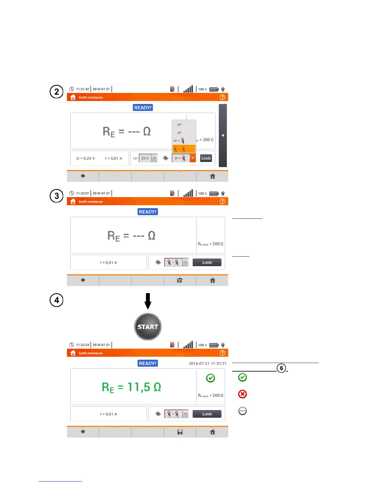
Select the clamps + clamps
option in the measurement
menu.
Select other settings in ac-
cordance with sec-
tion 3.5.1.
The meter is ready for meas-
urement.
Live mode
I – interference current cur-
rently flowing through the ob-
ject
Limits
R
E MAX
– currently set earth re-
sistance limit
Press START to start the
measurement.
Read out the result.
Signal lights for the limit (sec-
tion 3.5.1 step )
the result is within the
set limit
the result is outside the
set limit
assessment not possible