List of Figures
Figure 1: Sonic 2024/2022 Block Diagram ............................................................................................ 19
Figure 2: Sonic 2024 Acoustic Centre ................................................................................................... 23
Figure 3: Sonic 2024 Acoustic Centre as Mounted ............................................................................... 23
Figure 4: Sonic 2022 Acoustic Centre ................................................................................................... 24
Figure 5: Sonic 2022 Acoustic Centre as Mounted ............................................................................... 24
Figure 6: Sonic 2024 and Sonic 2022 on the mounting frame ............................................................. 25
Figure 7: Top side of Receive Module .................................................................................................. 26
Figure 8: Receive Module Face ............................................................................................................. 26
Figure 9: Seated connectors (Sonic 2024 on left and Sonic 2022 on right) ........................................ 26
Figure 10: Connector wiggle - back and forth NOT up and down ........................................................ 26
Figure 11: Receive Module with cables connected .............................................................................. 27
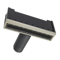
Figure 12: Sonic 2024 Projector ........................................................................................................... 27
Figure 13: Position the insulating bushing, then wrap threads with Teflon tape, then secure with flat
washer, locking washer and then nut. ................................................................................................. 27
Figure 14: Projector Stand-off .............................................................................................................. 28
Figure 15: Mounting the projector ....................................................................................................... 28
Figure 16: View of the mounted Projector; NB. Connector is facing protective fin ............................. 28
Figure 17: SV Probe mounted in block ................................................................................................. 28
Figure 18: Correct Orientation of the Sonic 2024 and the Sonic 2022 ................................................ 29
Figure 19: Typical over-the-side mount ............................................................................................... 31
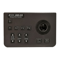
Figure 20: Sonar Interface Module (SIM) ............................................................................................. 33
Figure 21: Removal of trim to expose securing holes .......................................................................... 34
Figure 22: SIM Interfacing Physical Connections ................................................................................. 35
Figure 23: SIM Interfacing Guide (from label on top of the SIM) ......................................................... 35
Figure 24: SIM IEC mains connection and deck lead Amphenol connector ......................................... 36
Figure 25: Impulse connector ............................................................................................................... 36
Figure 26: Projector cable configuration .............................................................................................. 37
Figure 27: TTL input/output (PPS and Sync In/Out) schematic ............................................................ 38
Figure 28: Sonic Control Icon on desktop ............................................................................................. 41
Figure 29: Sonic Control 2000 .............................................................................................................. 41
Figure 30: Windows XP Internet Properties ......................................................................................... 42
Figure 31: IP and Subnet mask setup ................................................................................................... 43
Figure 32: Sonic Control Network setup .............................................................................................. 44
Figure 33: Set INS IP ............................................................................................................................. 44
Figure 34: Set IP Time Expired .............................................................................................................. 44
Figure 35: Command prompt-ipconfig/all ............................................................................................ 45
Figure 36: Sensor communication settings .......................................................................................... 47
Figure 37: Trigger In/Out Options ........................................................................................................ 48
Figure 38: Sonar Operation Settings window ....................................................................................... 49
Page 13 of 210
Version 5.0 Rev r002
Date 05-08-2014