Figure 120: Gyro Calibration Method 2 example .............................................................................. 113
Figure 121: Idealised concept of Gyro Calibration Method 2 ............................................................ 113
Figure 122: CTD Probe ....................................................................................................................... 116
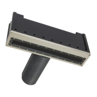
Figure 123: Time of Flight SV probe ................................................................................................... 117
Figure 124: Deploying a sound velocity probe via a winch or A - Frame ........................................... 120
Figure 125: Rough log, kept during survey operations...does not need to be neat, but must contain
all pertinent information ................................................................................................................... 125
Figure 126: Smooth log; information copied from real-time survey log ........................................... 126
Figure 127: Vessel Horizontal and Vertical reference system ........................................................... 128
Figure 128: Sonic 2024/2022 Acoustic Centre ................................................................................... 128
Figure 129: Sonic 2024/2022 axes of rotation ................................................................................... 131
Figure 130: Latency Data collection ................................................................................................... 132
Figure 131: Roll data collection .......................................................................................................... 133
Figure 132: Roll data collections ........................................................................................................ 133
Figure 133: Pitch data collections ...................................................................................................... 134
Figure 134: Yaw data collection ......................................................................................................... 135
Figure 135: In 1822 Daniel Colloden used an underwater bell to calculate the speed of sound under
water in Lake Geneva, Switzerland at 1435 m/Sec, which is very close to recent measurements. .. 141
Figure 136: Concept of refraction due to different sound velocities in the water column ............... 142
Figure 137: Sound velocity profile ..................................................................................................... 142
Figure 138: Refraction Error indication .............................................................................................. 143
Figure 139: Concept of Spherical Spreading ...................................................................................... 144
Figure 140: Concept of Cylindrical Spreading .................................................................................... 145
Figure 141: Single Head ROV Installation scheme A .......................................................................... 153
Figure 142: Single Head ROV Installation scheme B (Preferred) ....................................................... 153
Figure 143: Dual Head ROV Installation scheme A ............................................................................ 154
Figure 144: Dual Head ROV Installation scheme B (Preferred) ......................................................... 154
Figure 145: Sonic 2024 power supply current waveform. Peak current is 1.770A at 48V. Sonar
settings: pulse width = 100us, Tx Power = 221dB, Freq = 400 kHz. ................................................... 156
Figure 146: Sonic 2022 power supply current waveform. Peak current is 1.340A at 48V. Sonar
setting: pulse width = 100us, Tx Power = 221dB, Freq = 400 kHz. .................................................... 156
Figure 147: Inrush current to 2024 head during power up, 20 ms window. ..................................... 156
Figure 148: Inrush current to the 2024 head during power up, 1 second window. .......................... 157
Figure 149: Power supply choke installation on 48VDC power ......................................................... 157
Figure 150: SIM Controller Power Connections ................................................................................. 158
Figure 151: J6 Connector on SIM Controller board ........................................................................... 158
Figure 152: ROV installation block diagram with the SIM top-side ................................................... 159
Figure 153: ROV installation block diagram with the SIM controller board mounted in the vehicle
electronics bottle and GPS (ZDA or UTC formats) and PPS signals are supplied by top-side equipment
........................................................................................................................................................... 159
Page 16 of 210
Version 5.0 Rev r002
Date 05-08-2014
Part No. 96000001