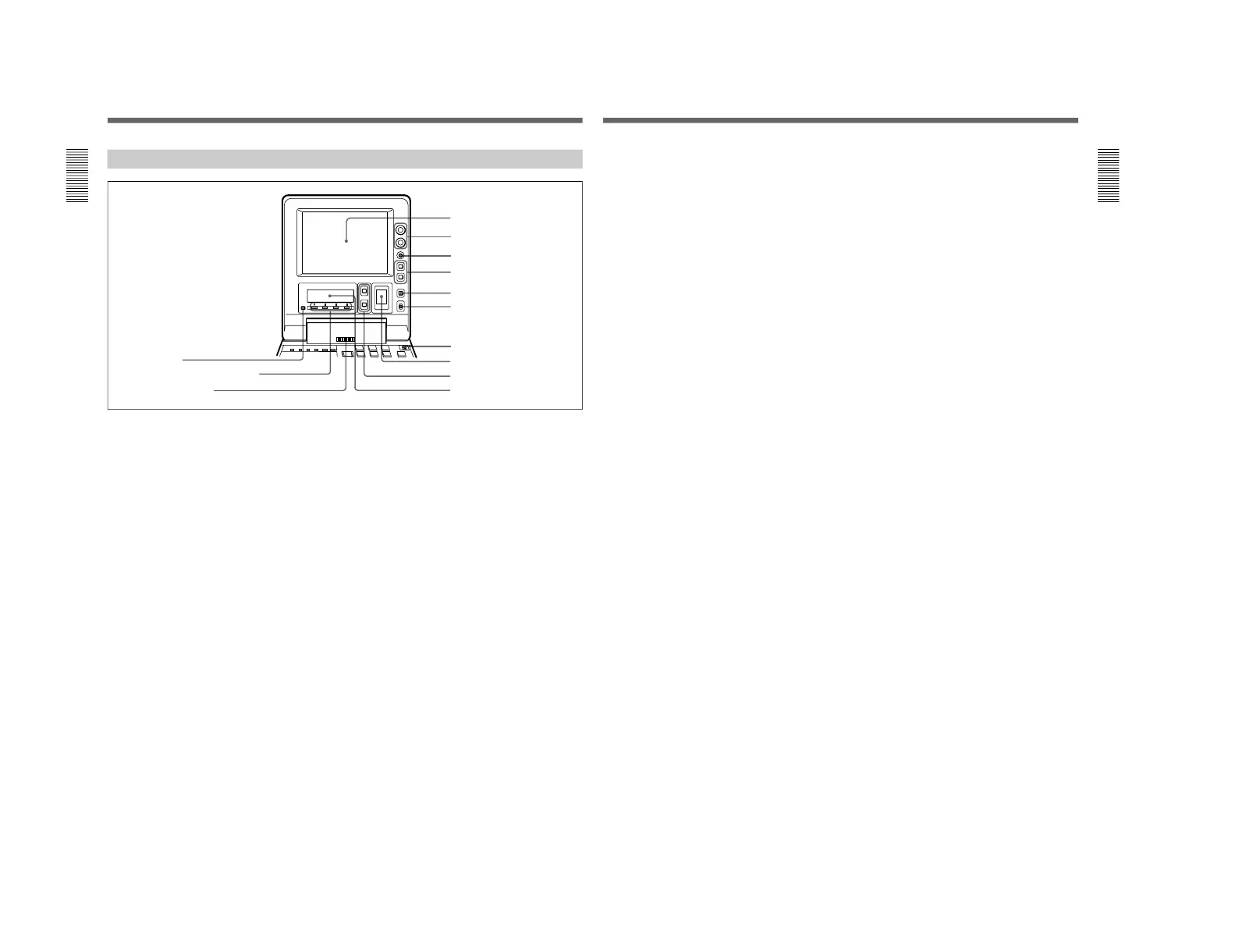
Location and Function of Parts
Chapter 1 Overview
14
Chapter 1 Overview
1 LCD monitor
Displays the playback or E-E pictures
1)
. Time data,
status information, and setup menus, etc. are
superimposed on the LCD monitor.
2 BRIGHT (brightness)/CONTRAST knob
Adjusts the brightness and contrast of the LCD
monitor 1. Adjustments have no effect on the
recorded or output video.
3 WARNING indicator
Lights when the battery is exhausted or an error
occurs.
It flashes when the end of battery power is near.
4 Timecode operation buttons
HOLD button: Stops the progress of the timecode
generator. Press this button before setting
timecode or user bits to hold those values.
RESET button: Press this to reset the preset data of
CNT (counter value) or TC (timecode) or UB
(user bit) indication in the sub LCD !º. Resetting
the CNT value erases all edit points that have been
set.
Use this button also when resetting the setup menu
to its factory default settings.
For more information, see “Setting Time Data” on page 61.
For information about how to reset the setup menu to its
factory default settings, see the section “Resetting the menu
settings to their factory default values” page 105.
5 COUNTER SELECT button
Alternately selects CNT (counter value), TC
(timecode), and UB (user bits) as the time data used in
editing and displayed in the sub LCD !º.
6 LIGHT (backlight on/off) switch
Turns the backlights of the sub LCD !º and audio
level meter 8 on and off.
You can also use the LIGHTSW setting of the sub LCD menu
to turn the LCD monitor power on and off. For details, see
page 74.
7 METER switch
Selects the audio channel whose level is displayed by
the audio level meter 8.
CH-1/2: Display the recording, playback, and E-E
levels of audio channels 1 and 2.
CH-3/4: Display the recording, playback, and E-E
levels of audio channels 3 and 4.
Display Panel
1 LCD monitor
2 BRIGHT (brightness)/
CONTRAST knob
3 WARNING indicator
4 Timecode operation buttons
5 COUNTER SELECT button
6 LIGHT switch
7 METER switch
8 Audio level meter
9 UP and DOWN buttons
!º Sub LCD
!£ PAGE button
!™ Sub LCD operation buttons F1 to F4
!¡ Audio monitor speaker
1) E-E pictures: “E-E” stands for “Electric to Electric”. In
E-E mode, the video and audio signals that are input to
the VCR’s recording circuitry do not pass through any
.........................................................................................................................................................................................
magnetic conversion circuits but instead are output via
electric circuits only. The pictures output in E-E mode are
referred to as E-E pictures.
Chapter 1 Overview
Chapter 1 Overview
15
8 Audio level meter
Displays the recording and playback audio levels of
two (CH-1/2 or CH-3/4) of the four audio channels
(CH-1 to CH-4), as selected with the METER switch
7.
9 UP and DOWN buttons
Press to make settings in the sub LCD menu.
For more information about the sub LCD menu, see “Sub
LCD Menu Home Page and Sub LCD Operation Buttons”
on page 66.
!º Sub LCD
Displays time data, status information, remaining
battery capacity, remaining tape time, sub LCD menu,
setup menu and error messages.
For more information about the sub LCD menu, see “Sub
LCD Menu Home Page and Sub LCD Operation Buttons”
on page 66.
!¡ Audio monitor speaker
Plays the mixed audio signal of the audio channels
selected with the MONITOR item in the sub LCD
menu. Adjust the volume with the LEVEL knob on the
front control panel. You cannot monitor sound from
the speaker when headphones are connected to the
HEADPHONES jack.
For more information about the MONITOR item, see page
71.
!™ Sub LCD operation buttons F1 to F4
Select items in the sub LCD menu.
For more information about the sub LCD menu, see “Sub
LCD Menu Home Page and Sub LCD Operation Buttons”
on page 66.
!£ PAGE button
Switches between pages in the sub LCD menu.
For more information about the sub LCD menu, see “Sub
LCD Menu Home Page and Sub LCD Operation Buttons”
on page 66.