Location and Function of Parts
Chapter 1 Overview
18
Chapter 1 Overview
4 EDIT button
Press together with the PLAY button 9 to perform
manual editing.
To monitor E-E mode
You can monitor input signals in E-E mode by
pressing this button from stop mode. The button lights
when pressed, and the input signals selected with the
ASSEMBLE or INSERT buttons appear in E-E mode.
To return to the original picture, press the STOP
button 5. You can view E-E video during playback,
search, fast forward, and rewind by pressing this
button. The E-E video continues for as long as the
button is kept pressed.
5 STOP button
Press this button, lighting it, to stop playback or
recording. When you stop playback, the LCD monitor
displays E-E or still picture playback, depending on
the PB/EE setting in the sub LCD menu.
Setting setup menu item 105 to ON or LIMIT causes
this button to flash when the input video signal and the
reference video signal are asynchronous.
6 Search button and indicators
Press to enter search mode. (The JOG or SHUTTLE
indicator lights)
In shuttle mode, you can start playback at preset speed
by rotating the shuttle dial to the desired position and
pressing this button.
When setup menu item 129 is set to ON, this button
functions as a pause button. You can use the pause
button to make a pause during sequential recording
carried out using two DSR-70/70P units.
7 STANDBY indicator
Lights when the tape drum is rotating with tension
applied (standby on). It goes out when the drum stops
rotating and tension is released (standby off).
To protect the tape, the unit normally changes to
standby off when stop mode continues for longer than
8 minutes. If you operate a dial or any of the tape
transport buttons except STOP 5 while the unit is in
this state, the unit changes to standby on and enters the
mode of the button or dial that you pressed.
Press the ENTRY/SHIFT and STOP 5 buttons at the
same time to switch between standby on and standby
off manually.
For more information about tape protection, see the setup
menu items in the 500s on page 108.
8 F FWD (fast forward) button
Press this button, lighting it, to fast forward the tape.
By pressing the TRIM+/MARK button and this button
simultaneously, you can cue up to any Mark IN point
or cue point provided by ClipLink log data.
For details, see Chapter 6 “ClipLink Operation” on page
91.
9 PLAY button
Press this button, lighting it, to start playback.
Recording starts when you press this button together
with the REC/SEQ button 3, and manual editing
starts when you press this button together with the
EDIT button. If you press this button only during
recording or manual editing, recording or manual
editing stops and the unit returns to playback mode.
!º Jog and shuttle dials
To search in shuttle mode, rotate the outer ring (shuttle
dial). To search in jog mode, press the inner ring (jog
dial) until it clicks and then rotate. Rotate in the
clockwise direction to search in the forward direction
(the FORWARD indicator lights), and rotate in the
counterclockwise direction to search in the reverse
direction (the REVERSE indicator lights).
For more information about search, see “Finding Edit
Points — Search” on page 49.
!¡ SERVO indicator
Lights when the drum and capstan are servo-locked.
!™ REW (rewind) button
Press this button, lighting it, to rewind the tape.
Alternatively, by pressing the TRIM+/MARK button
and this button simultaneously, you can cue up to any
Mark IN point or cue point provided by ClipLink log
data.
For details, see Chapter 6 “ClipLink Operation” on page
91.
!£ PLAYER/RECORDER buttons and indicators
When two DSR-70/70P units are combined and
connected via the REMOTE (9-pin) connectors or DV
connector (when DSBK-140 is installed), press to
control one unit from another.
PLAYER button: The buttons of the editing and
tape transport sections on the recorder side of the
control panel work to control the player.
RECORDER button: The buttons of the editing and
tape transport sections on the recorder side of the
control panel work to control the recorder itself.
!¢ EJECT button
Press to eject the cassette or open the cassette
compartment !§. The button lights while the cassette is
being ejected.
!∞ REC INHI switch
When on, recording to the tape is inhibited, regardless
of the setting of the cassette’s REC/SAVE switch.
(The REC INHI indicator 2 lights.)
!§ Cassette compartment
Insert a cassette here. Press the EJECT button !¢ to
open the compartment.
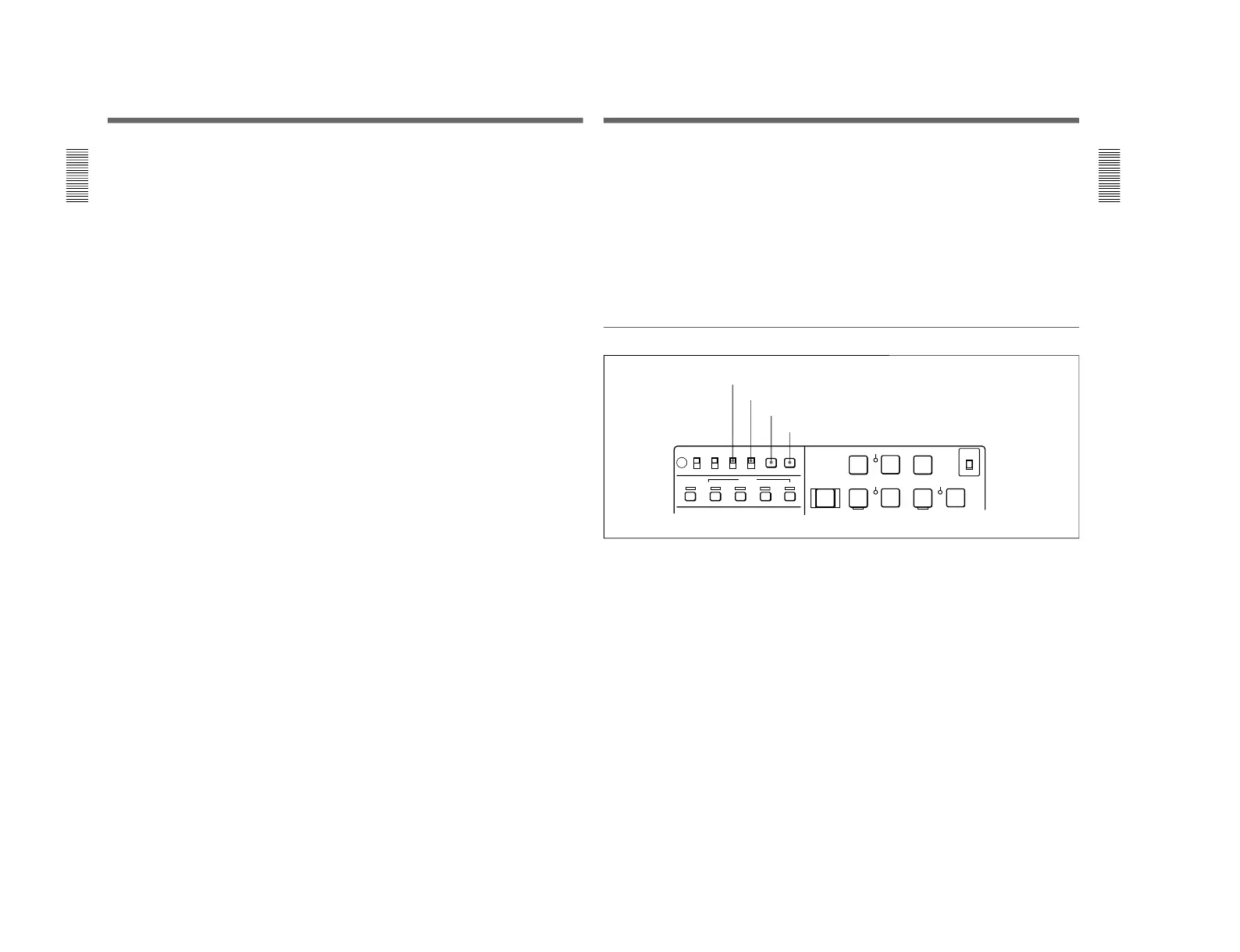
Timecode, character and setup menu section
1 TC INT/EXT (internal/external timecode)
switch
Selects the timecode to use.
INT: Use the timecode generated by this unit’s built-
in timecode generator.
EXT: The external timecode input to the TC IN
connector.
2 CHARACTER switch
Selects whether or not to display timecode and other
superimposed text data on the LCD monitor and the
output from the VIDEO OUTPUT 2 (SUPER)
connector.
1 TC INT/EXT switch
2 CHARACTER switch
3 MENU button
4 SET button
3 MENU button
Use for setup menu operations. The setup menu
appears on the LCD monitor when you press this
button, and the original display appears when you
press it again.
For more information about setup menu operations, see
Chapter 7 “Setup Menu” on page 101.
4 SET button
Use to make setup menu settings, timecode settings,
and user bit settings.
For more information about setup menu operations, see
Chapter 7 “Setup Menu” on page 101. For more
information about timecode and user bit settings, see
“Setting Time Data” on page 61.