6-4
DSR-70/70P
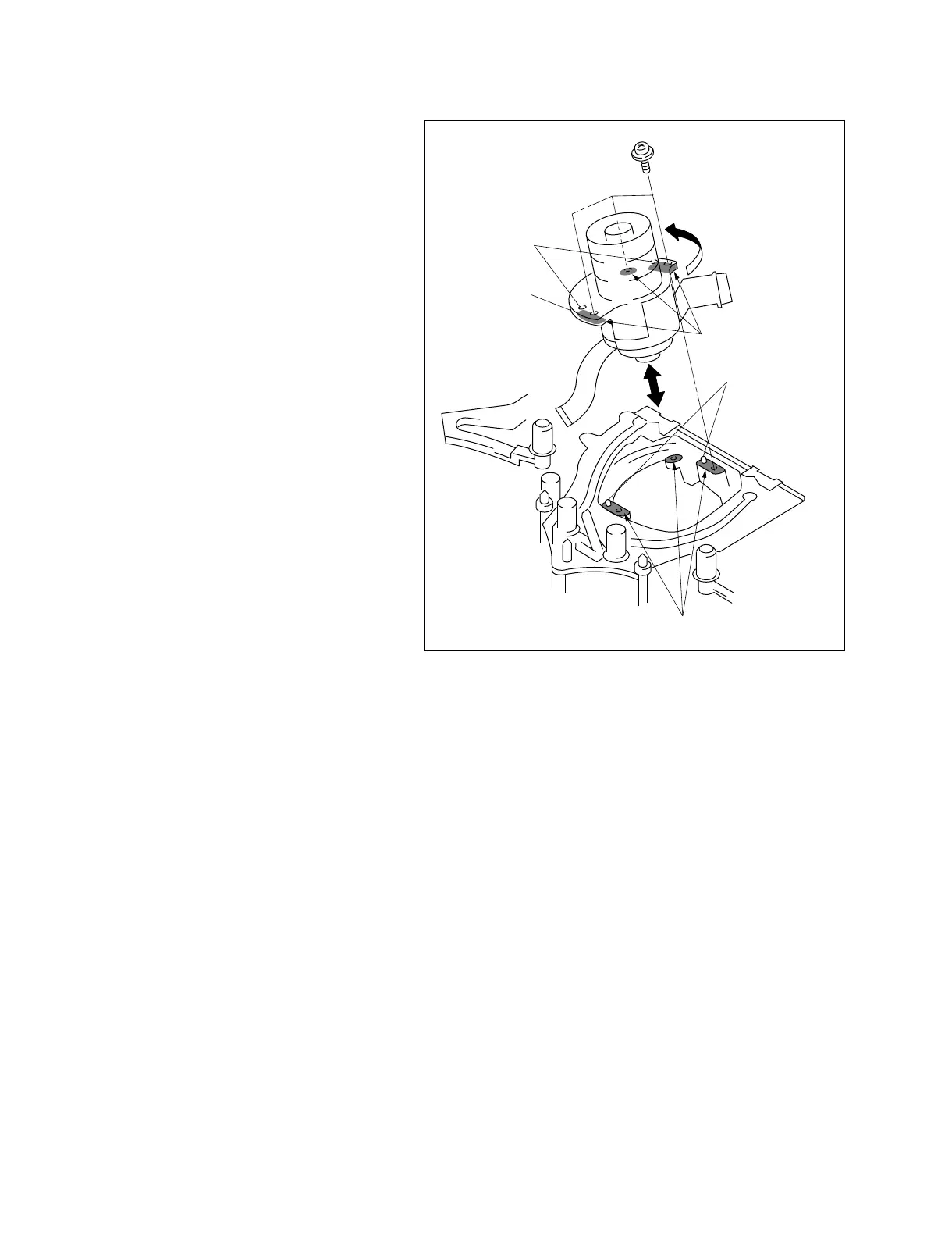
Mounting surface
Precision screw
(1.4x3.5)
Positioning hole
Drum assembly
Mounting surface (rear)
Positioning pin
5. Place the DSR-70/70P horizontally.
6. Remove the three precision screws securing the
drum assembly from the mechanism assembly
and remove the drum assembly while taking care
not to let it touch the various guides.
Attachment
7. Clean the mounting surface of the new drum and
the mounting surface of the MD chassis using the
cleaning cloth moistened with cleaning fluid.
8. Align the two positioning pins of the MD chassis
with the positioning holes in the bottom of the
drum assembly, then insert the drum assembly
into the MD chassis.
9. While pushing the drum assembly in the
direction of the arrow (turning counter
clockwise), fix the drum assembly with the three
screws.
10.Connect the connectors and attach the
disassembled parts by reversing the removal
procedure from step 4 to 1.
11.Clean the tape running surface of the drum
assembly using the cleaning cloth moistened
with cleaning fluid.
12.After cleaning, wipe the cleaned surface two or
three times with a dry cloth.
Adjustment After Replacement
. Perform the tape path adjustment.
(Refer to section 7.)
. Perform the RF switching position adjustment.
(Refer to section 7-3.)
. Perform the EQ adjustment. (Refer to section 4.)
 Loading...