64
Chapter 4 Time Data and Sub LCD Menu
Chapter 4 Time Data and Sub LCD Menu
2
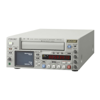
Press the HOLD button.
The first digit of the time data
(hours:minutes:seconds:frames) in the sub LCD
begins to flash.
To set all digits to 0
Press the RESET button.
3
Confirm the JOG indicator lights, and select jog
mode if not. (Shuttle mode is not recommendable.)
4
Select the digit to set by rotating the jog dial.
The flashing digit changes to the digit on the right
when you rotate the jog dial clockwise, and to the
digit on the left when you rotate it
counterclockwise.
5
Set the value for the flashing digit by rotating the
jog dial while pressing the search button.
6
Repeat steps 4 and 5 until you finish setting all
digits.
7
Press the SET button.
If the F-RUN/R-RUN item is set to F-RUN, the
timecode starts to advance immediately.
To set timecode to the current time
1
Set the F-RUN/R-RUN item to F-RUN and the
DF/NDF in the sub LCD menu to DF (for DSR-70)
(see page 73).
2
Carry out steps 1 to 6 of “To set an initial
timecode value” (on previous page) to set the
timecode to a time slightly ahead of the current
time.
3
Press the SET button at the instant when the
current time matches the displayed timecode.
To set user bits
You can record up to 8 hexadecimal digits of
information (date, time, event number, etc.) in the
timecode track.
Proceed as follows.
1
Press the COUNTER SELECT button and select
UB.
2
Carry out steps 2 to 7 of “To set an initial
timecode value”.
Settings are made in hexadecimal (0, 1, 2,... 8, 9,
A, B,... E, F).
Setting Time Data
Chapter 4 Time Data and Sub LCD Menu
Chapter 4 Time Data and Sub LCD Menu
65
Synchronizing the Internal
Timecode Generator With an
External Signal — External Lock
You can synchronize the internal timecode generator
of this unit by inputting an external timecode signal
(LTC).
To synchronize to an external timecode
signal
Connect the external timecode (LTC) signal to the TC
IN connector, and set the TC INT/EXT switch to the
EXT position.
This starts the synchronization of the internal timecode
generator to the external timecode signal. Once the
synchronization is achieved, the internal timecode
generator continues to be synchronized even when the
external timecode signal is disconnected.
Note
When the input mode is SDTI or i.LINK (the SDTI or
i.LINK indicator is present in the subsidiary LCD),
then setting the TC INT/EXT switch to the EXT
position automatically synchronizes the internal
timecode generator to the timecode transferred through
the SDTI (DSBK-150) or i.LINK (DSBK-140)
interface.
Note that when the TC INT/EXT switch is set to EXT,
the advance mode and frame count mode (DSR-70
only) are automatically set as follows.
Advance mode: free running
Frame count mode (DSR-70 only): the same as the
external timecode signal (drop frame or non-drop
frame)
Checking the synchronization to the
external signal
Press the STOP button to stop this unit, then press the
REC/SEQ button.
Watch the time counter display, and check that the
values displayed coincide with the external timecode
values.
 Loading...