62
Chapter 4 Time Data and Sub LCD Menu
Chapter 4 Time Data and Sub LCD Menu
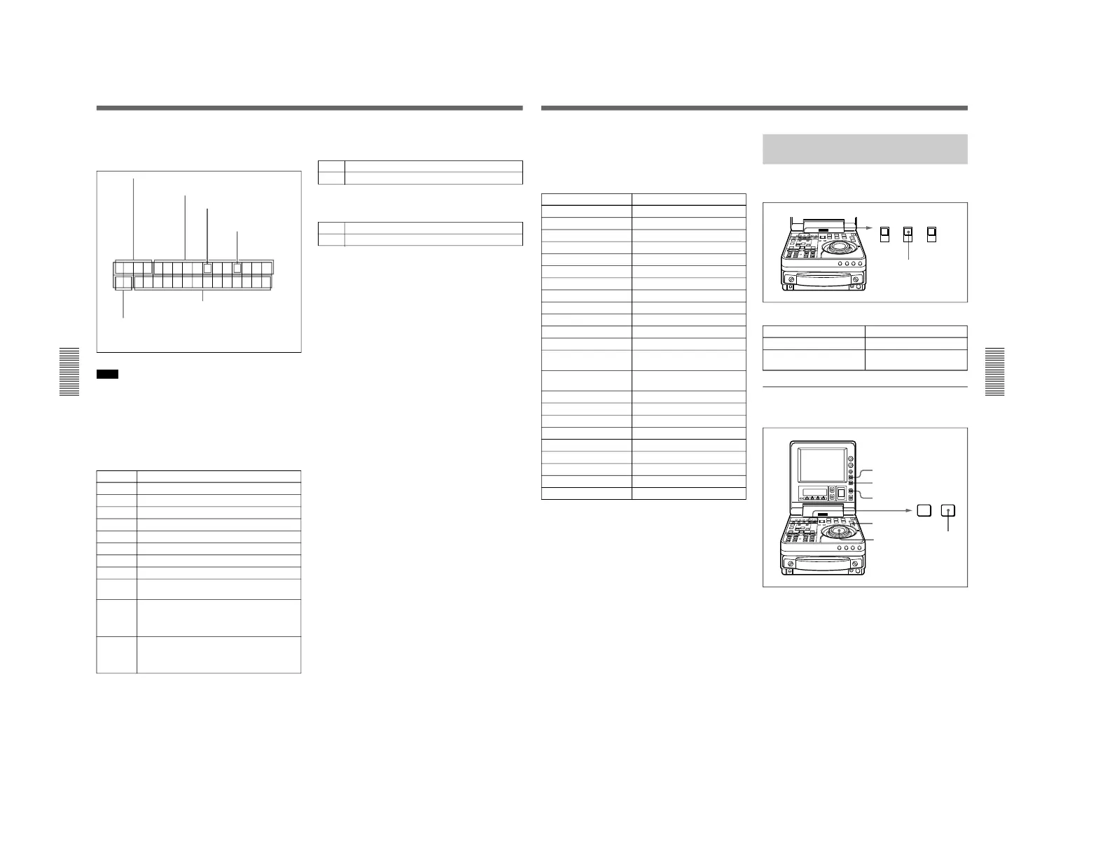
Information displayed
The figure below shows the time data and operation
status that can be superimposed.
Note
The example above shows the factory default
configuration.
You can use setup menu item 005 to display a different
type of time data in the second line as well.
For details, see page 102.
1 Time data type
Display Meaning
CNT Count value of the time counter (COUNTER)
TCR Timecode reader timecode data
UBR Timecode reader user bits data
TCG Timecode generator timecode data
UBG Timecode generator user bits data
IN IN point time data
OUT OUT point time data
AI Audio IN point time data
DUR The duration between any two of the three edit
points (IN, OUT, AUDIO IN)
T*R Time code data from time code reader. The
asterisk indicates an interpolation by the time
code reader to make up for the time code data
not correctly read from the tape.
U*R User bit data from the time code reader. The
asterisk indicates that last data is retained by
the time code reader, as the new data has not
been read correctly from the tape.
2 Timecode reader drop-frame mark (for DSR-70
only)
3 Timecode generator drop-frame mark
(for DSR-70 only)
4 Recorder/player selection
The indication changes depending on the status of the
RECORDER/PLAYER indicators.
No display: When the RECORDER and PLAYER
indicators are both not lit.
P: The PLAYER indicator is lit.
R: The RECORDER indicator is lit.
Setting Time Data
Chapter 4 Time Data and Sub LCD Menu
Chapter 4 Time Data and Sub LCD Menu
63
5 Operating mode
The ■ mark, indicating an auto editing segment, may
appear at the rightmost position.
The contents displayed other than the ■ mark are
listed on next page.
a) “+2.0” in the left box is an example of playback speed
indication.
Setting an Initial Value and
Recording Timecode
Set the switches and sub LCD menu items as shown
below.
Sub LCD menu settings
Item Setting
F-RUN/R-RUN Desired setting
DF/NDF Desired setting
(general settings page) (for DSR-70)
To set an initial timecode value
Perform the following procedure.
1
Press the COUNTER SELECT button and select
TC.
RESET button
Display Operating Mode
CASSETTE OUT No cassette loaded
TAPE UNTHREAD Tape not yet threaded
STANDBY OFF Standby off mode
T. RELEASE Tension release mode
STOP Stop mode
F. FWD Fast forward mode
REW Rewind mode
PREROLL Preroll mode
PLAY Playback mode (servo unlock)
PLAY LOCK Playback mode (servo lock)
REC Recording mode (servo unlock)
REC LOCK Recording mode (servo lock)
SEQ REC Sequential recording mode
(servo unlock)
SEQ REC LOCK Sequential recording mode
(servo lock)
EDIT Editing mode (servo unlock)
EDIT LOCK Editing mode (servo lock)
JOG STILL Jog mode still playback
JOG FWD Forward jog
JOG REV Reverse jog
SHUTTLE +2.0 Shuttle mode (playback speed)
a)
PREVIEW Preview mode
AUTO EDIT Auto edit mode
REVIEW Review mode
(Continued)



 To Next Page