Soundcraft Vi6™ User Guide Page 5 - 5
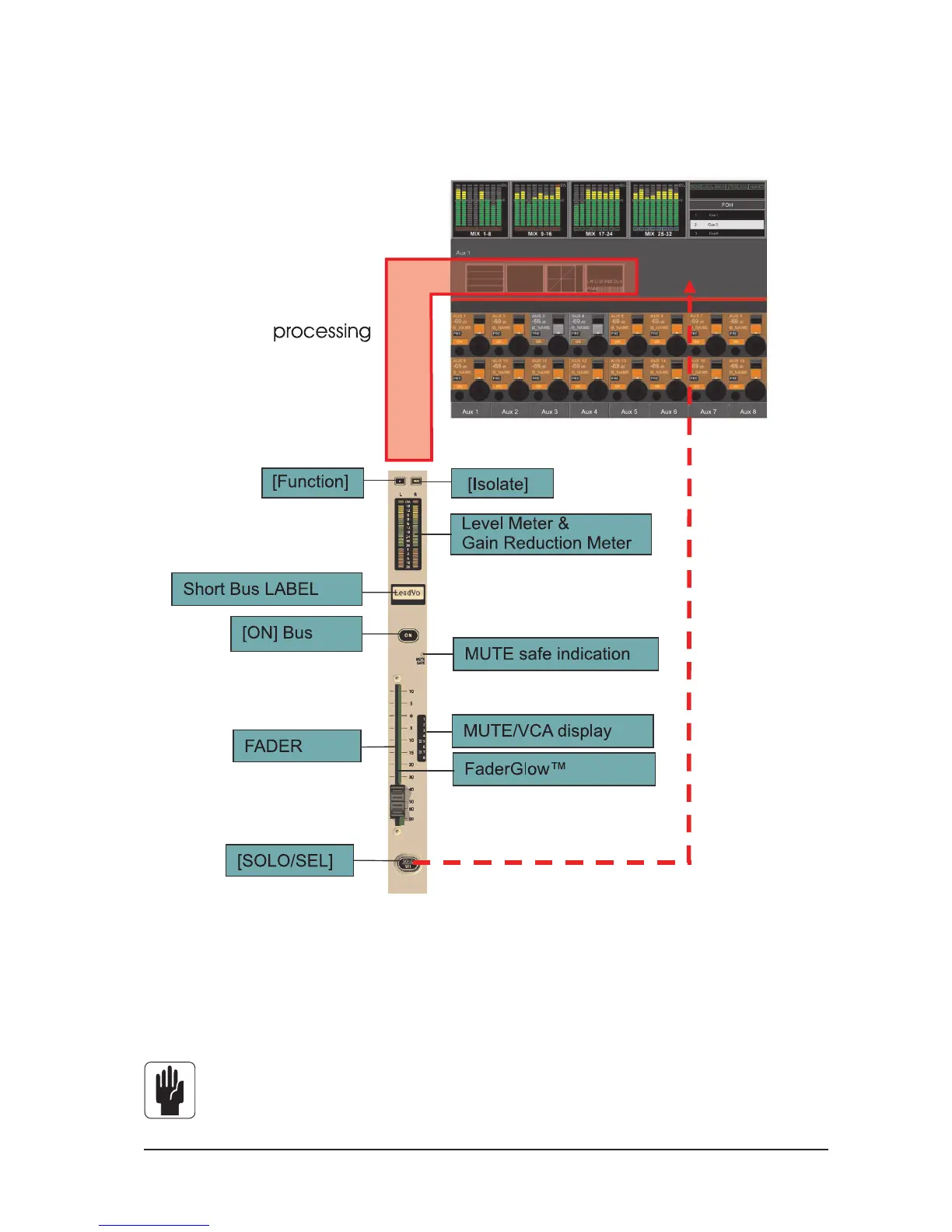
MASTER BAY OUTPUT STRIPS
The first way of controlling and changing the parameters of the 32 output busses described earlier is as
follows.
Figure 5-3. A Master Bay Strip.
In order to select the desired output from the 32 possible choices, the correct fader page, A-D, must first
be assigned to the master bay (see Figure 8-5 for the keys). Once this is done, the user can select the
desired fader to control the output level, and pressing its [SOLO/SEL] key opens the processing Area in the
Master screen (see Figure 5-4).
HINT: [METER LOCK] must be off, otherwise the processing strip will not be displayed. If multiple
Output Solo are activated the processing for the last-pressed Master Solo is displayed.
 Loading...