Technical data are subject to change without notice.
© Copyright SPM 2002-04. 71650.B
SPM Instrument AB • Box 504 • S-645 25 Strängnäs • Sweden
Tel +46 152 225 00 • Fax +46 152 15075 • info@spminstrument.se • www.spminstrument.se
SPM measuring points
The rules for the selection of SPM measuring points have a very practical purpose. We are trying to
catch low energy signals which are getting weaker the farther they travel and the more they are
bounced about inside a piece of metal. We know that they lose strength when they cross over from
one piece of metal to another (oil between the pieces helps). We cannot know, for all bearing
applications, how much of the strength of the signal emitted by the bearing will reach the
measuring point. However, of necessity we try to apply general evaluation rules, i. e. treat all
measured signals as if they were of the same quality.
The rules for SPM measuring points try to assure that most of them are ”within tolerances” and
that the green-yellow-red condition zones are valid:
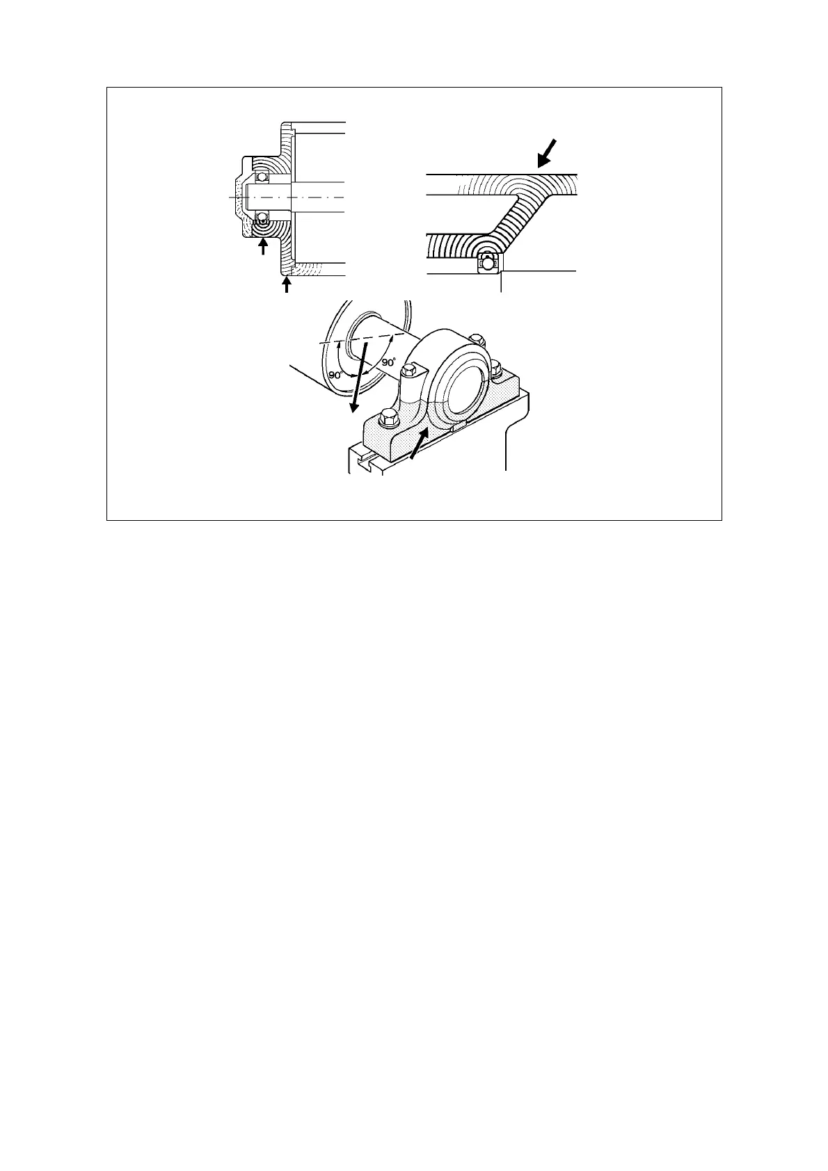
1 The signal path between bearing and measuring point shall be as short and straight as
possible.
2 The signal path must contain only one mechanical interface, that between bearing and
bearing housing.
3 The measuring point shall be located in the load zone of the bearing.
Short means up to 75 mm (3 in.), but that depends also on how straight the path is: bends cause re-
and deflections whose effect is hard to judge. The load zone is the load carrying half of the bearing
housing, normally the lower one. Allow for the pull of belts or other forces which can shift the load
to one side. Use the probe to find the spot yielding the strongest signal. When a measuring point
cannot conform to the rules (because an ideal spot cannot be reached), make allowance for a
weaker signal.
Measuring
point
Load
1. Straight and
short path
2. No interface!
3. In the load zone
of the bearing
12 SPM measuring points and transducers