Technical data are subject to change without notice.
© Copyright SPM 2002-04. 71650.B
SPM Instrument AB • Box 504 • S-645 25 Strängnäs • Sweden
Tel +46 152 225 00 • Fax +46 152 15075 • info@spminstrument.se • www.spminstrument.se
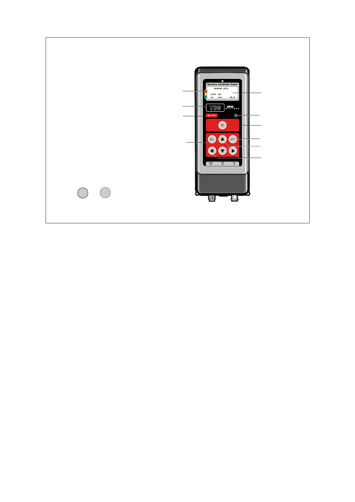
Instrument layout, screen and keys
Holding down any key for a second switches on the instrument at the function last used. The
display, 4 lines of 16 characters each, shows the active menu. Measuring techniques are selected
with the RIGHT/LEFT arrows, measuring points (if loaded in logger mode) with UP/DOWN. Menus
for RPM and temperature measurement appear when the respective probe is connected.
The green-yellow-red marking beside the display is the condition scale. After a normalized SPM or
a VIB measurement with machine class input, an arrow points at one of the colours.
PEAK is a light indicator active during SPM measurements. The round window opposite to the right
is a light sensor controlling the LED backlight of the display. At the top, an arrow marks the
position of the proximity reader receiving the ID data from coded measuring points.
The functions of the keypad vary, depending the active menu. The instruments now contain too
many functions to limit each key to a single action. The exception is the M key, used exclusively to
start measurements.
Pressing the keys M and ENT simultaneously starts continuous reading. The measuring results are
being updated until any key but M is pressed and held down to interrupt this mode.
The ENT key confirms selections, saves values and settings, and leaves functions. The other keys
are mainly used to move between or within displays. UP/DOWN increases/decreases marked
values.
Instrument layout
1 Reader for CondID
TM
2 Display 4x16 char.
3 Condition scale
4 Instrument type
5 Peak indicator
6 Light sensor
7 Measuring key
8 Up/down keys
9 Left/right keys
10 Enter key
11 Set key
12 Input connectors
ENT
M
+
Continuous read
1
3
4
5
8
9
2
6
7
10
12
11
General description, setup 3