Technical data are subject to change without notice.
© Copyright SPM 2002-04. 71650.B
SPM Instrument AB • Box 504 • S-645 25 Strängnäs • Sweden
Tel +46 152 225 00 • Fax +46 152 15075 • info@spminstrument.se • www.spminstrument.se
SPM
TLT 18
dBm 16
dBc 9 dBi 26
Basic data
Condition:
red - bad (≥35)
yellow - caution (21–34)
green - good (≤ 20)
SET
M
SPM
PROBE
dBm 16
dBc 9 dBi 26
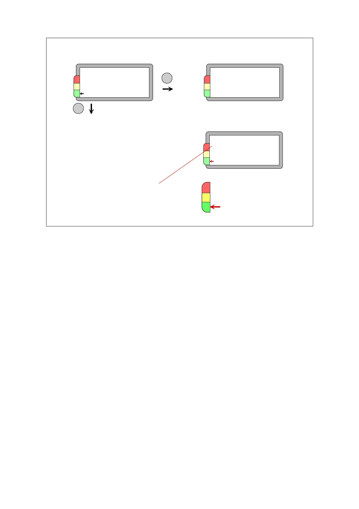
Measuring dBm/dBc
SPM measurement
Back in the SPM menu, you can connect the transducer to the measuring point and press the M key
to start a measurement. It takes approx. 2 - 10 seconds, during which the connected transducer
type is displayed: PROBE for hand-held probe, TRA for the quick connect transducer and the
standard 40000 transducer, TMU for a transducer matching unit in the transducer line.
The two measuring results are the maximum value dBm and the carpet value dBc. Depending on
the dBm value, an arrow will point at the green, yellow or red field of the condition scale.
When TLT test is on, the instrument will also display the result of a transducer line test. At TLT-
values from 15 upward, there is normally no signal loss due to a faulty transmission between
transducer and instrument. If the value is below 15, or if it is deteriorating from a previously higher
value, you have to check cables and connectors for poor connections and moisture.
When you get high readings (yellow and red zone), you should immediately verify their nature and
probable cause. Do not give the verdict ”bearing damage” before making a further investigation.
As a first measure:
• see if the peak indicator is blinking.
• use the earphone to identify the shock pulse pattern.
• use the probe transducer to measure on and outside of the bearing housing to identify the
shock pulse source.
SPM
TLT 18
dBm 16
dBc 9 dBi 26
New result dBm/dBc
TLT = Transducer line test
Normal acceptance
limit = 15
Display SPM: dBm/dBc
SPM measurement 21