Technical data are subject to change without notice.
© Copyright SPM 2002-04. 71650.B
SPM Instrument AB • Box 504 • S-645 25 Strängnäs • Sweden
Tel +46 152 225 00 • Fax +46 152 15075 • info@spminstrument.se • www.spminstrument.se
Balancing single - plane rotors
The T30 can be used for simple balancing work which is accurate enough to reduce machine
vibration to an acceptable level. The method requires no dismantling of the rotor. It is suitable for
machines with a rotational speed greater than 600 rpm and with a single-plane rotor, i.e. a rotor
which is considerably larger in diameter than in thickness.
Balancing Method
After measuring the vibration of the rotor bearing, a trial weight is fastened to the rotor. Three
more readings are taken, with the trial weight moved through 120° after each run. Weight and
position of the correction mass are calculated graphically, using the balancing form and a pair of
compasses.
First Reading
Measure vibration severity on the rotor bearing in the radial direction which yields the highest
value (usually horizontal). Use the same measuring point for all following readings, and run the
machine at the same speed. Record the result V
0
of this measurement.
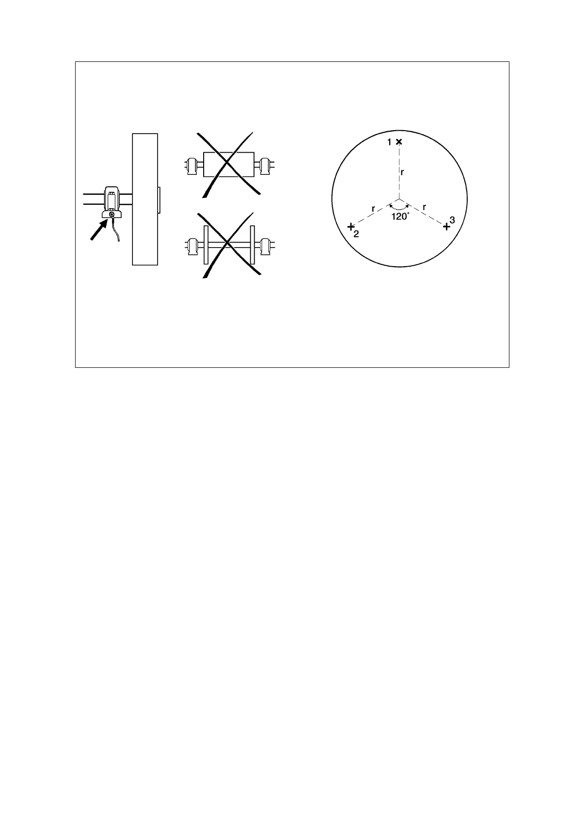
Trial Points
Find and mark three trial points on the rotor where a weight can be attached. These points must be
at an equal radial distance r from the shaft, and 120° removed from each other. Number the points
counter clockwise 1, 2 and 3.
Trial Weight
The trial weight should be heavy enough to create a moderate out-of-balance in the rotor (10-30
grams). It should be screwed or clamped onto the rotor. Its weight M
t
in grams should be
determined beforehand, as accurately as possible.
Second to Fourth Reading
Attach the trial weight to point 1, run the machine up to normal speed, measure and record the
vibration severity V
1
. Repeat the measurement with the trial weight at points 2 and 3, record the
results V
2
and V
3
.
Rotor and measuring point Trial points on the rotor
Balancing with T30 69