Technical data are subject to change without notice.
© Copyright SPM 2002-04. 71650.B
SPM Instrument AB • Box 504 • S-645 25 Strängnäs • Sweden
Tel +46 152 225 00 • Fax +46 152 15075 • info@spminstrument.se • www.spminstrument.se
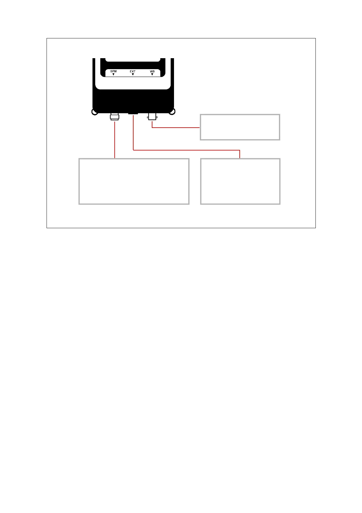
Instrument layout, inputs
The instruments have three different input connectors:
SPM A TNC connector receiving a shock pulse transducer (probe, quick connect transducer, or
a cable to a measuring terminal.
EXT A modular jack receiving temperature probe, tachometer probe, earphone, and the cable
to the communication module for data transfer.
VIB A BNC connector receiving vibration transducer.
The instruments can monitor the connected SPM transducer type, e. g. a shock pulse transducer
with or without transducer matching unit TMU, and react accordingly.
In data logger mode and for long-time recording, three transducers can be simultaneously con-
nected: SPM, VIB, and either temperature or tachometer probe. The display shows measuring
points and measuring techniques in the order they are downloaded, and you can scroll through the
list without disconnecting a transducer.
In manual mode, you can have both a shock pulse and a vibration transducer connected all the
time. The display switches to the respective function when a temperature or tachometer probe is
connected. To leave the function, disconnect the probe.
During SPM measurements you can connect the earphone and switch between SPM measuring and
earphone mode.
SPM
• Shock pulse transducer with
probe
• Shock pulse transducer with
quick connector
• Cable to measuring terminal
EXT
• Temperature probe
• Tachometer probe
• Earphone
• Communication module
VIB
• Vibration transducer
Input
connectors
4 General description, setup